SLVUC46D March   2021  – November 2023


  1.   1
  2.   Abstract
  3.   Trademarks
  4. 1Introduction
    1. 1.1 Overview
      1. 1.1.1 Purpose and Scope
  5. 2Evaluation Hardware Overview
    1. 2.1 Connections Overview
    2. 2.2 Connection Details
      1. 2.2.1 Common Connectors and Headers Across all EVM Variants
      2. 2.2.2 MCU Reset and User Button
      3. 2.2.3 Communication Interfaces
      4. 2.2.4 Supply Input
      5. 2.2.5 Current Limit Header (RIPROPI)
      6. 2.2.6 Device Signal and Control Header
      7. 2.2.7 Device Signal Test Points
    3. 2.3 LED Indicators
    4. 2.4 Headers and Connectors (Hardware Device Variant)
    5. 2.5 Headers and Connectors (SPI variant)
  6. 3EVM GUI Control Application
    1. 3.1 MSP430 FET Drivers
    2. 3.2 Cloud-based GUI
    3. 3.3 Local Installation
  7. 4EVM GUI Operation
    1. 4.1 Hardware Setup
    2. 4.2 Launching the DRV824x_DRV814x-Q1EVM GUI Application
    3. 4.3 Using the DRV824x_DRV814x-Q1EVM GUI Application
      1. 4.3.1 Register Map Page (SPI Device Variant)
      2. 4.3.2 Driver Control Page (SPI Device Variant)
      3. 4.3.3 Driver Control Page (HW Device Variant)
      4. 4.3.4 Updating Firmware
  8. 5Revision History

MCU Reset and User Button

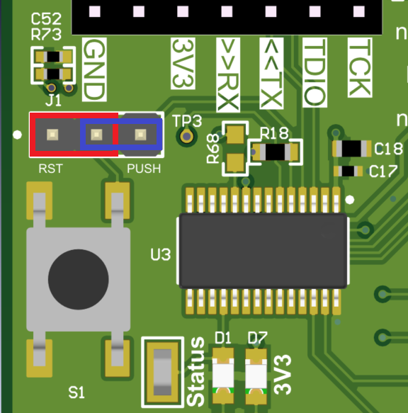
The small tactile push button is typically used to reset the MCU Figure 2-2. Typically resetting the MCU is not necessary, however the MCU automatically clears the nFAULT indicator on initial power-up if the user finds the fault indicator is set due to cycling the power on the external supply. This is normal (nFAULT always comes up asserted on the DRV824x and DRV814x devices).

A jumper is installed shorting pins 1 and 2 on header J1 for the MCU reset function. If a firmware reset is necessary, then the push button is pressed once and released. Following a reset, a proper startup is indicated by the blinking STATUS LED. If the jumper is moved to pins 2 and 3 on J1, then this routes the button to a spare GPIO pin on the MSP430 MCU, and can be used for personal purposes in the firmware. Beginning with version 0.22 of the firmware, an interrupt subroutine (ISR) has been assigned to this GPIO input, and automatically puts the DRV824x device in PH/EN mode, and energize the output OUT1 terminal (or OUT terminal of the DRV814x device) at 25% duty cycle on the first press of the User button with a 12 V power supply connected to the connector J14, BAT+ and GND screw terminals and the Micro-USB connected. Pressing the button again disables the output. This can be repeated with the same on/ off behavior. The user can connect a brushed DC motor across OUT1 and OUT2 terminals of the DRV824x EVM or OUT and GND of the DRV814x EVM, or simply an oscilloscope.
Note: No diagnostics are enabled in this simple test case – open load detection is not active
When in this test mode, the STATUS LED (D1) is fully on when the output is active, and returns to approximately 1 Hz blinking when the output is off with an SPI EVM or an approximately 0.1 Hz blinking with an HW EVM. After completion of the standalone EVM testing, TI recommends to position the jumper settings back to pins 1 and 2.

GUID-20210421-CA0I-WXNH-QL3P-DVMJM6M28KPP-low.png Figure 2-2 MCU Reset and User Button