SLVUC47A July 2021 – August 2021 TPSM5601R5
3 Test Results
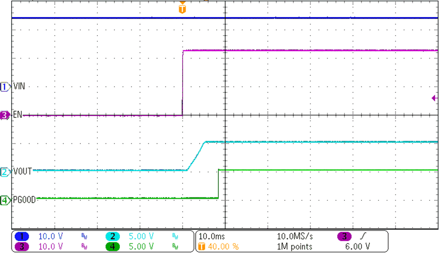
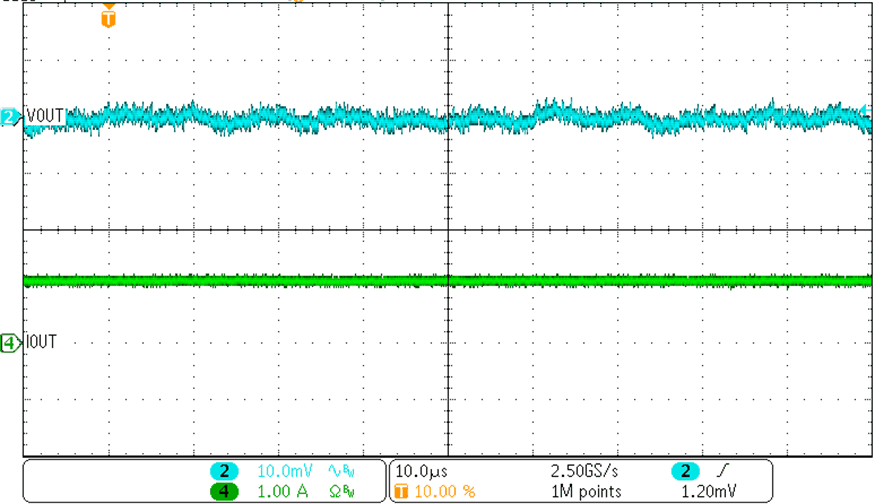
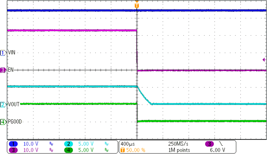
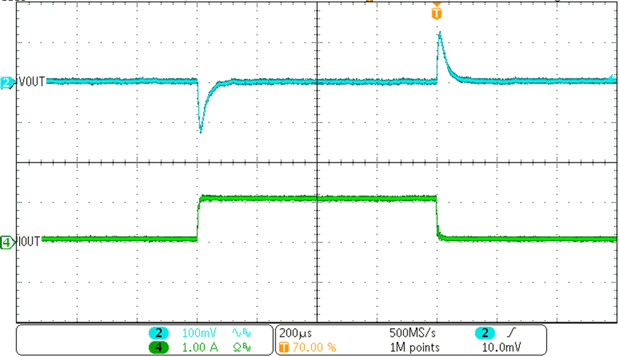
Figure 3-1 through Figure 3-4 demonstrate the performance of the TPSM5601R5EVM under the following condition of a 24-V input voltage, 5-V output voltage, and 1-A load.
 Figure 3-1 ENABLE Start-Up Waveform
 Figure 3-3 Output Voltage
Ripple
 Figure 3-2 ENABLE Shutdown Waveform
 Figure 3-4 Transient
Performance