TPS51396AEVM Evaluation Module
1 Trademarks
All trademarks are the property of their respective owners.
2 Introduction
TPS51396A DC/DC converter is a synchronous buck converter designed to provide up to a 8-A output. The input (VIN) is rated for 4.5 V to 24 V. The TPS51396A uses a proprietary DCAP3 Control mode. Rated input voltage and output current range for the evaluation module are given in Table 2-1. The high-side and low-side MOSFETs are incorporated inside the TPS51396A package along with the gate-drive circuitry. An external divider allows for an adjustable output voltage. Additionally, the TPS51396A provides 1.3ms internal soft start or external soft start, under voltage lockout inputs and power good output.
| EVM | INPUT VOLTAGE RANGE | OUTPUT CURRENT RANGE |
|---|---|---|
| TPS51396AEVM | 4.5 V to 24 V | 0 A to 8 A |
3 Performance Specification Summary
A summary of the TPS51396AEVM performance specifications is provided in Table 3-1. Specifications are given for an input voltage of VIN = 12 V and an output voltage of 1.0 V, unless otherwise specified. The TPS51396AEVM is designed and tested for VIN = 4.5 V to 24 V. The ambient temperature is 25°C for all measurements, unless otherwise noted.
| SPECIFICATION | TEST CONDITIONS | MIN | TYP | MAX | UNIT |
|---|---|---|---|---|---|
| Input voltage | 4.5 | 12 | 24 | V | |
| Output voltage setpoint | 1.0 | V | |||
| FB voltage | TJ = 25°C | 594 | 600 | 606 | mV |
| Output current range | 0 | 8 | A | ||
| Soft start time | External soft start time | 2.6 | ms | ||
| Operating frequency | 600k | Hz | |||
| Mode | Light load operating mode | ECO | |||
| Over current | Valley current set point | 9.8 | A |
TPS51396A supports six different kinds of mode by selecting divider resister on mode pin. Please refer Table 3-2.
In this TPS51396AEVM board, mode can be selected to 600kHz/ECO and 600kHz/OOA by Mode Jumper. If you want to select other mode, please replace mode divider resister according to below table.
| R_Top(kΩ) | R_Bottom (kΩ) | LIGHT LOAD OPERATION | FREQUENCY (kHz) |
|---|---|---|---|
| 330 | 5.1 | Eco | 600 |
| 330 | 15 | Eco | 800 |
| 330 | 27 | Eco | 1000 |
| 200 | 27 | OOA | 600 |
| 150 | 33 | OOA | 800 |
| 160 | 51 | OOA | 1000 |
4 Schematic and List of Materials
This section presents the TPS51396AEVM schematic and List of Materials.
 Figure 4-1 Schematic
| DES | QTY | DESCRIPTION | PART NUMBER | MAN |
|---|---|---|---|---|
| C2 | 1 | Capacitor, ceramic, 1 µF, 25 V, ±10%, X5R, 0603 | C1608X5R1E105K080AC | TDK |
| C3, C4, C5 | 3 | Capacitor, ceramic, 22 µF, 35 V, ±20%, X5R, 1206 | C3216X5R1V226M160AC | TDK |
| C1, C6, C7, C15 | 4 | Capacitor, ceramic, 0.1 µF, 50 V, ±10%, X7R, 0603 | C1608X7R1H104K080AA | TDK |
| C14 | 1 | Capacitor, ceramic, 0.018 µF, 16 V, ±10%, X7R, 0603 | GRM188R71C183KA01D | MuRata |
| C8, C9, C10, C11, C12 | 5 | Capacitor, ceramic, 22 µF, 10 V, +±20%, X7S, 1206 | C3216X7S1A226M160AC | TDK |
| C13 | 1 | Capacitor, ceramic, 47 pF, 50 V, +±5%, C0G/NP0, 0603 | 06035A470JAT2A | AVX |
| D1 | 1 | Diode, Zener, 3.6 V, 500 mW, SOD-123 | MMSZ4685T1G | ON Semiconductor |
| J1, J2 | 2 | Terminal block, 5.08 mm, 2x1, brass, TH | ED120/2DS | On-Shore Technology |
| J3 | 1 | Header, 100 mil, 2x1, tin, TH | PEC02SAAN | Sullins Connector Solutions |
| J4 | 1 | Header, 100 mil, 3x1, tin, TH | PEC03SAAN | Sullins Connector Solutions |
| J5 | 1 | Header, 100 mil, 3x2, tin, TH | PEC03DAAN | Sullins Connector Solutions |
| L1 | 1 | Inductor, shielded drum core, Superflux, 680 nH, 17 A, 0.0035 Ω, SMD | 744311068 | Wurth Elektronik |
| R7 | 1 | Resistor, 120 kΩ, 5%, 0.1 W, AEC-Q200 grade 0, 0603 | CRCW0603120KJNEA | Vishay-Dale |
| R10 | 1 | Resistor, 51 kΩ, 5%, 0.1 W, AEC-Q200 grade 0, 0603 | CRCW060351K0JNEA | Vishay-Dale |
| R11 | 1 | Resistor, 5.11 kΩ, 1%, 0.1 W, AEC-Q200 grade 0, 0603 | CRCW06035K11FKEA | Vishay-Dale |
| R8 | 1 | Resistor, 332 kΩ, 1%, 0.1 W, AEC-Q200 grade 0, 0603 | CRCW0603332KFKEA | Vishay-Dale |
| R5 | 1 | Resistor, 100 kΩ, 1%, 0.1 W, AEC-Q200 grade 0, 0603 | CRCW0603100KFKEA | Vishay-Dale |
| R1, R3 | 2 | Resistor, 0 Ω, 5%, 0.1 W, AEC-Q200 grade 0, 0603 | CRCW06030000Z0EA | Vishay-Dale |
| R2 | 1 | Resistor, 51.1 Ω, 1%, 0.1 W, AEC-Q200 grade 0, 0603 | CRCW060351R1FKEA | Vishay-Dale |
| R6 | 1 | Resistor, 30.1 kΩ, 1%, 0.1 W, AEC-Q200 grade 0, 0603 | CRCW060330K1FKEA | Vishay-Dale |
| R4 | 1 | Resistor, 20.0 kΩ, 1%, 0.1 W, AEC-Q200 grade 0, 0603 | CRCW060320K0FKEA | Vishay-Dale |
| R12 | 1 | Resistor, 27.4 kΩ, 1%, 0.1 W, AEC-Q200 grade 0, 0603 | CRCW060327K4FKEA | Vishay-Dale |
| R9 | 1 | Resistor, 200 kΩ, 1%, 0.1 W, AEC-Q200 grade 0, 0603 | CRCW0603200KFKEA | Vishay-Dale |
| SH-J1, SH-J2, SH-J3 | 3 | Shunt, 100 mil, gold plated, black | SNT-100-BK-G | Samtec |
| TP1, TP4, TP5, TP6, TP7, TP12, TP13 | 7 | Test point, miniature, red, TH | 5000 | Keystone |
| TP8, TP10, TP15, TP16 | 4 | Test point, miniature, black, TH | 5000 | Keystone |
| TP2, TP3, TP9, TP11, TP14 | 5 | Terminal, turret, TH, Triple | 1598-2 | Keystone |
| U1 | 1 | 4.5-V to 24-V input, 8-A synchronous step-down voltage regulator, RJE0020A (VQFN-HR-20) | TPS51396ARJER | Texas Instruments |
5 Board Layout
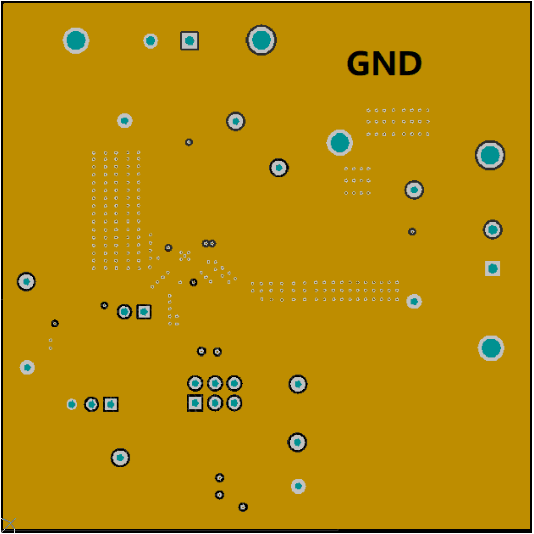
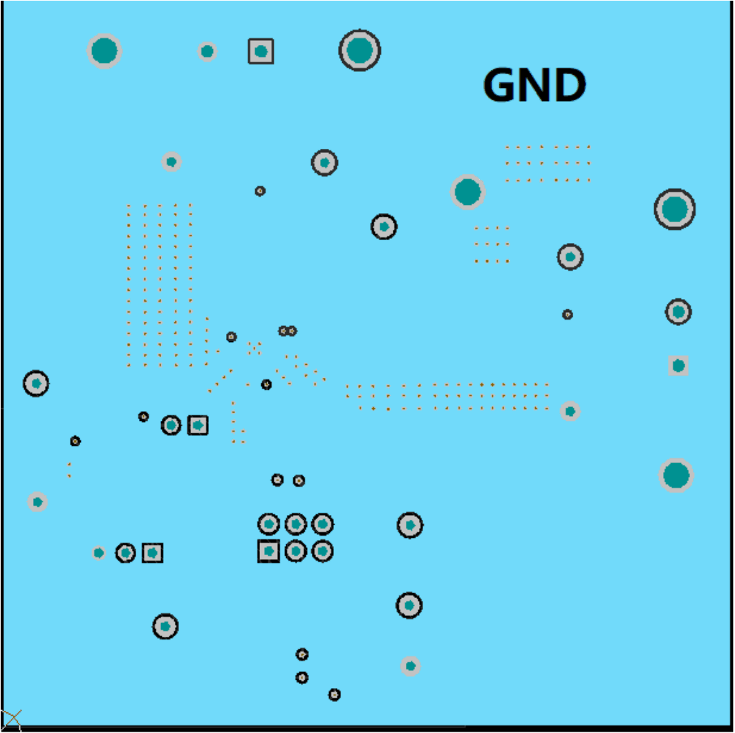
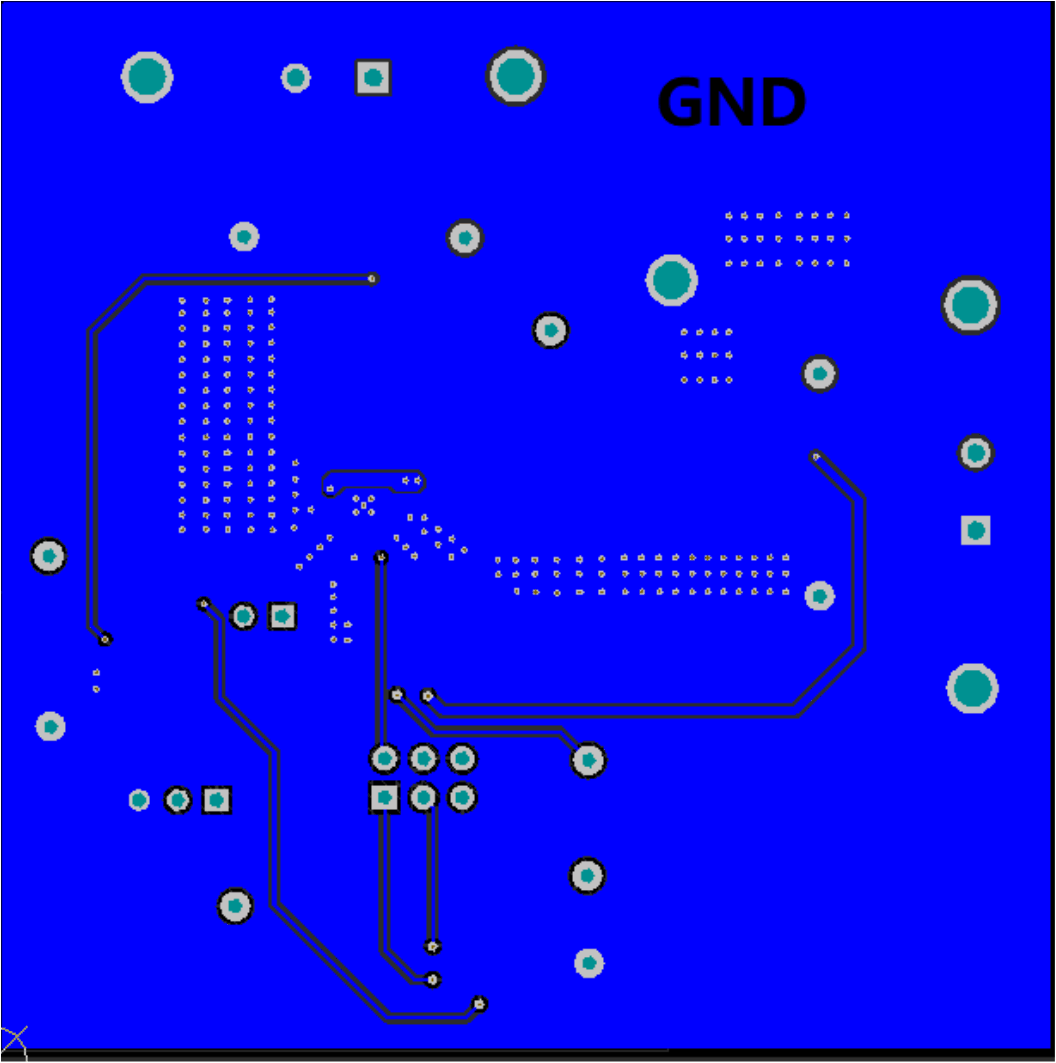
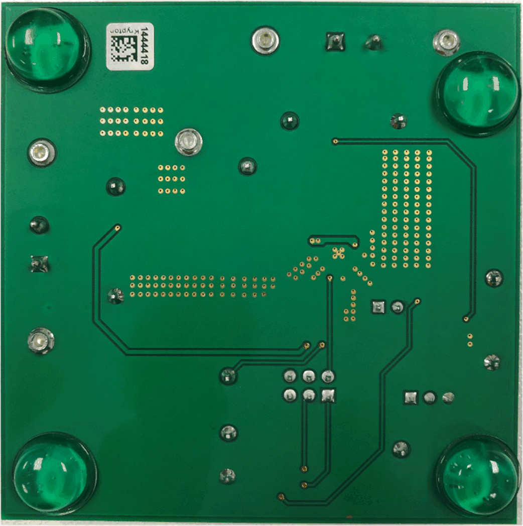
This section provides a description of the TPS51396AEVM board layout and layer illustrations. The board layout for the TPS51396AEVM is shown in below figures. The top-side layer of the EVM is laid out in a manner typical of a user application. The top and bottom layers are 2-oz copper, and internal layers are 1-oz copper.
The top layer contains the main power traces for VIN, VOUT, and SW. Also on the top layer are connections for the remaining pins of the TPS51396A and the majority of the signal traces. There is a large area filled with ground. The internal layer-1 and layer-2 are ground plane. The bottom layer is another ground plane with some additional signal. The top-side ground traces are connected to the bottom and internal ground planes with multiple vias placed around the board.
The input decoupling capacitors and bootstrap capacitor are all located as close to the IC as possible. Additionally, the voltage set point resistor divider components are kept close to the IC. The voltage divider network ties to the output voltage at the point of regulation. For the TPS51396A, an additional input bulk capacitor may be required, depending on the EVM connection to the input supply. Critical analog circuits such as the voltage set point divider, EN resistor, SS capacitor, MODE resistor, and AGND pin are terminated to quiet analog ground island.
 Figure 5-1 Component Placements
 Figure 5-2 Top Layer
 Figure 5-3 Internal Layer1
 Figure 5-4 Internal Layer2
 Figure 5-5 Bottom Layer
Figure 5-6 and Figure 5-7 are high revolution images of the EVM board.
 Figure 5-6 EVM Front View
 Figure 5-7 EVM Back View