SLVUCC0A October 2021 – December 2021 TPS2597
5.2 Overcurrent Test
Use the following instructions to perform the overcurrent test on the circuit breaker variant (TPS25974x) of TPS2597xx eFuse:
- Place jumper J16 to the appropriate position to obtain required blanking period as per Table 4-3.
- Set the input supply voltage VIN to 12 V and current limit of 10 A and enable the power supply.
- Place jumper J18 in s suitable position to set the required current limit as per Table 4-3.
- Apply an overload greater than the set current limit between VOUT and GND (while testing the current limit variant of TPS2597xx, use a resistive load to apply overcurrent). CC load is not recommended for the current limit test.
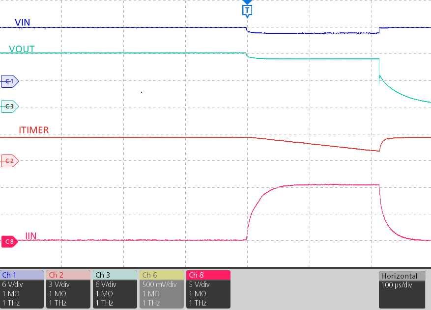
- The device allows the overload current for the programmed ITIMER period and then switches OFF.
Figure 5-3 shows an example of the circuit breaker test on the TPS2597EVM.
 Figure 5-3 Overcurrent Response of TPS25974x for 8-A
Current Limit Setting