SLVUCD3A November 2021 – August 2022 DRV8328
- Abstract
- 1Introduction
- 2Quick Start Guide
- 3Hardware and Software Overview
- 4Hardware Setup
- 5Firmware and GUI Application
-
6Schematics
- 6.1 DRV8328A/B/C/D
- 6.2 DRV8328C/D variant select
- 6.3 Status LEDs
- 6.4 LaunchPad Connectors and Connections
- 6.5 External 3.3V LDO
- 6.6 Power Stage and MOSFETs
- 6.7 Main Supply Input
- 6.8 Hall Sensor and Hall Power Selection
- 6.9 Connectors, Selectors, and Analog Control Interface
- 6.10 Voltage Sense and Protection
- Trademarks
- 7Revision History
3.4.1 DRV8328A/B Compatibility
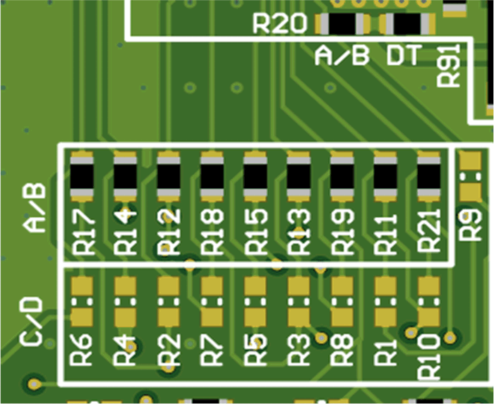
The DRV8328AEVM default is the DRV8328A (Hardware variant), but can also be compatible with the DRV8328B. The main difference is that DRV8328A operates in 6x PWM mode and DRV8328B operates in 3x PWM mode. Figure 3-7 shows the default resistors to select the A/B variant when the DRV8328A or DRV8328B is used. Ensure resistors R1-R10 are removed, C1 is removed, and resistors R11-R21 are populated (except R16).
 Figure 3-7 Resistors to populate for DRV8328A/B device
Table 3-3 shows the resistors to be only populated as well as their pin and functions.
Table 3-3 DRV8328A/B pinout, function, and populated resistors
DRV8328A/B Pin | Function | Populated Resistors |
|---|---|---|
18 | INHC | R11 |
19 | INHB | R12 |
20 | INHA | R13 |
21 | INLC | R14 |
22 | INLB | R15 |
23 | INLA | R17 |
24 | nFAULT | R18 |
25 | nSLEEP | R19 |
26 | VDSLVL | R20 |
27 | DT | R21 |