SLVUCF5A March   2022  – August 2022 DRV8329


  1.   Abstract
  2.   Trademarks
  3. 1Cautions and Warnings
  4. 2Introduction
  5. 3Quick Start Guide
  6. 4Hardware and Software Overview
    1. 4.1 Hardware Connections Overview – DRV8329AEVM + LAUNCHXL-F280049C
    2. 4.2 Connection Details
    3. 4.3 LED Lights
    4. 4.4 DRV8329AEVM Configurability
      1. 4.4.1 DRV8329A/B Compatibility
    5. 4.5 Interfacing DRV8329AEVM and LAUNCHXL-F280049C LaunchPad
  7. 5Hardware Setup
  8. 6Firmware and GUI Application
    1. 6.1 Connecting to the DRV8329AEVM-GUI
    2. 6.2 DRV8329x EVM GUI Quick Start Guide
    3. 6.3 Using the DRV8329x EVM GUI
  9. 7Schematics
    1. 7.1 DRV8329A/B
    2. 7.2 Status LEDs
    3. 7.3 LaunchPad Connectors and Connections
    4. 7.4 Power Stage and MOSFETs
    5. 7.5 Main Supply Input
    6. 7.6 Hall Sensor and Hall Power selection
    7. 7.7 Connectors, Selectors, and Analog Control Interface
    8. 7.8 Dead Time and CSA Gain Selection
    9. 7.9 Voltage Sense and Protection
  10. 8Revision History

Hardware Connections Overview – DRV8329AEVM + LAUNCHXL-F280049C

Figure 4-1 shows the major hardware blocks of the DRV8329AEVM. The DRV8329AEVM is designed for an input supply from 4.5-V to 60-V.
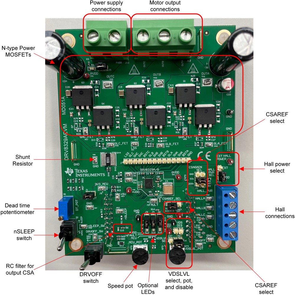
GUID-20220214-SS0I-PX63-MJ39-120MZ4GTNKHH-low.jpgFigure 4-1 Major hardware blocks of the DRV8329AEVM