SLVUCI7 July   2022 TPS22950-Q1


  1.   Abstract
  2.   Trademarks
  3. 1Introduction
    1. 1.1 Description
    2. 1.2 Features
  4. 2Electrical Performance
  5. 3Schematic
  6. 4PCB Layout
    1. 4.1 Setup
  7. 5Operation
  8. 6Test Configurations
    1. 6.1 On-Resistance (Ron) Test Setup
    2. 6.2 Rise Time Test Setup
  9. 7Bill of Materials (BOM)

On-Resistance (Ron) Test Setup

Figure 6-1 shows the typical setup for measuring on-resistance. The voltage drop across the switch is measured using the sense connections, and this result can be divided by the load current to calculate the Ron resistance.
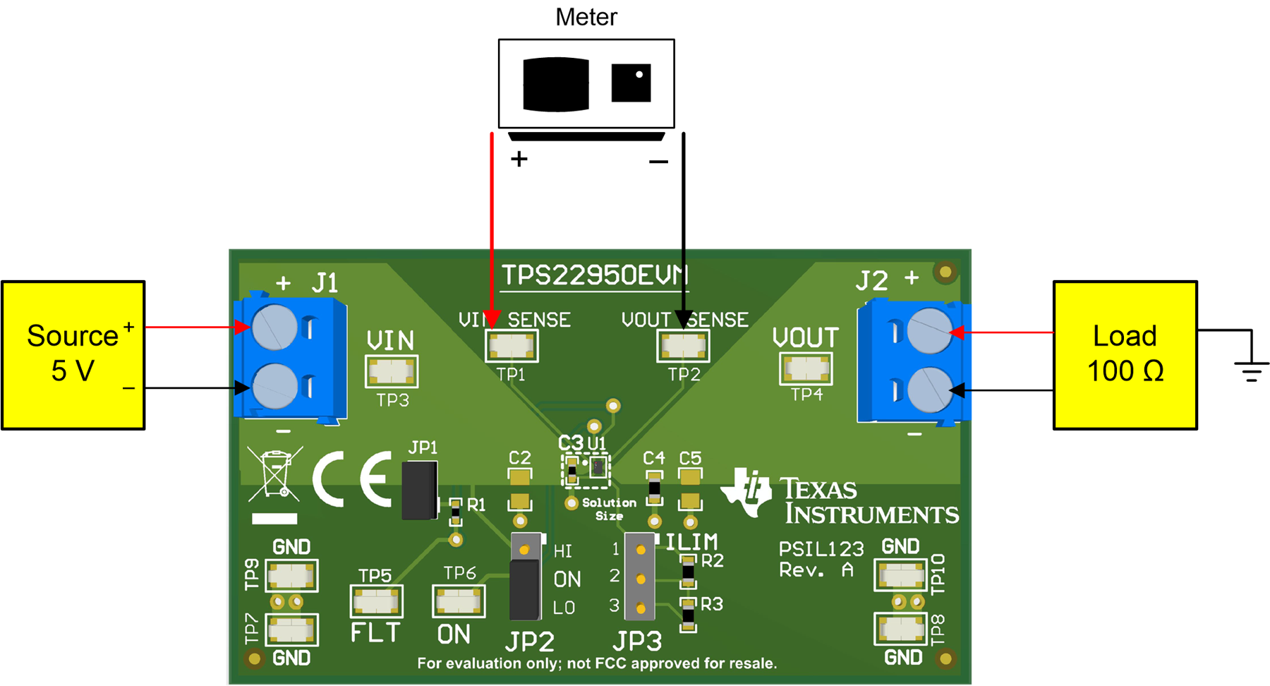
GUID-BF41FAA4-108A-448C-B88F-35A4CE8D9616-low.pngFigure 6-1 Ron Test Setup