SLVUCN5B July 2023 – July 2024 TPS7H6003-SP
4.2 PCB Layouts
 Figure 4-7 Top Solder Mask
(TPS7H6003EVM-CVAL)
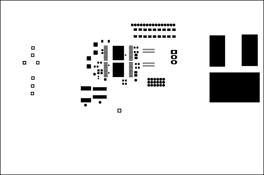 Figure 4-8 Top Solder Mask (TPS7H6013EVM-CVAL)
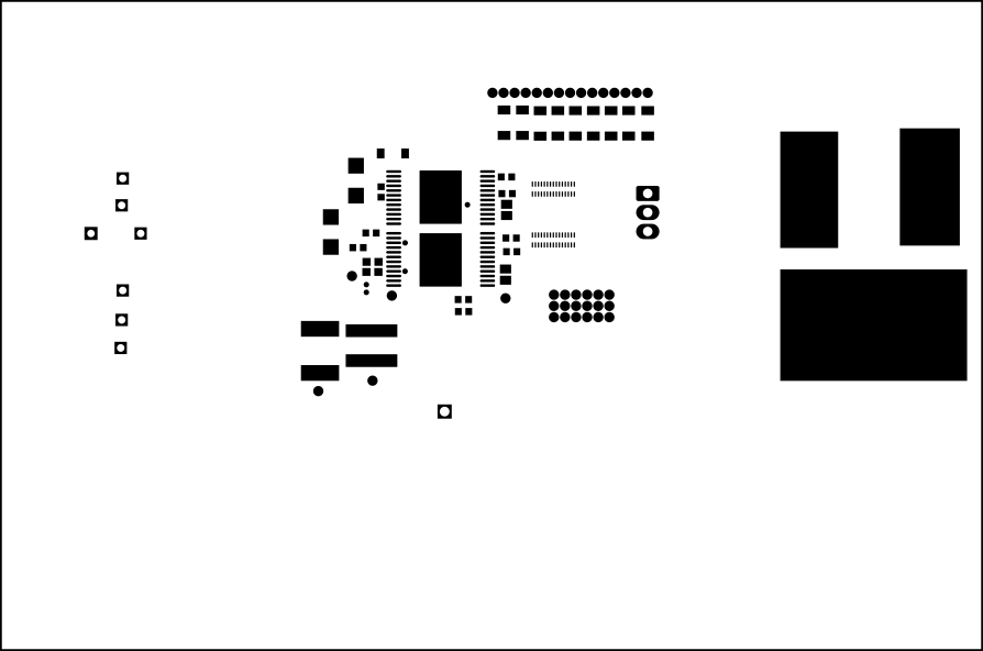 Figure 4-9 Top Solder Mask
(TPS7H6023EVM-CVAL)
 Figure 4-10 Top Overlay
(TPS7H6003EVM-CVAL)
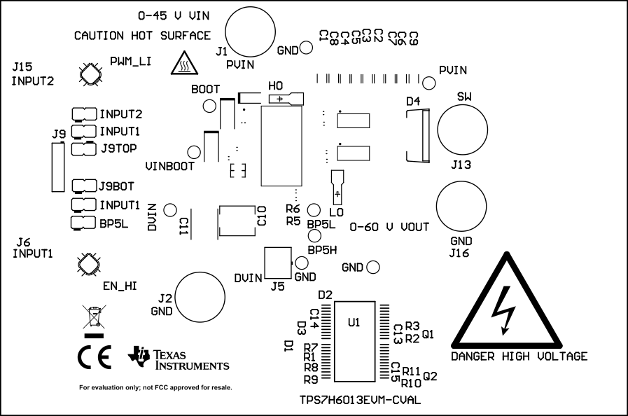 Figure 4-11 Top Overlay (TPS7H6013EVM-CVAL)
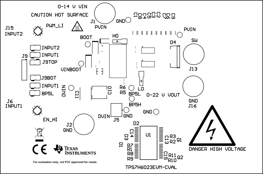 Figure 4-12 Top Overlay (TPS7H6023EVM-CVAL)
 Figure 4-13 Top Layer
(TPS7H6003EVM-CVAL)
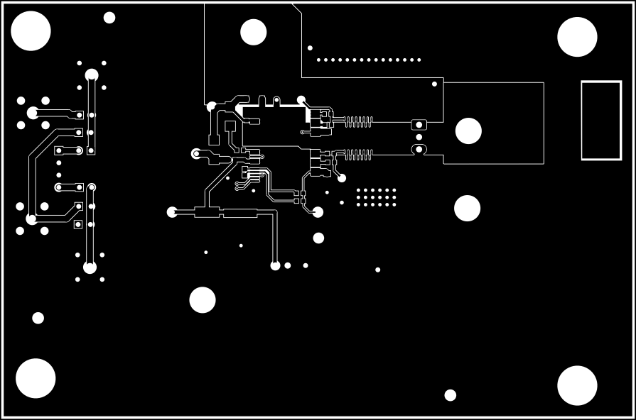 Figure 4-14 Top Layer (TPS7H6013EVM-CVAL)
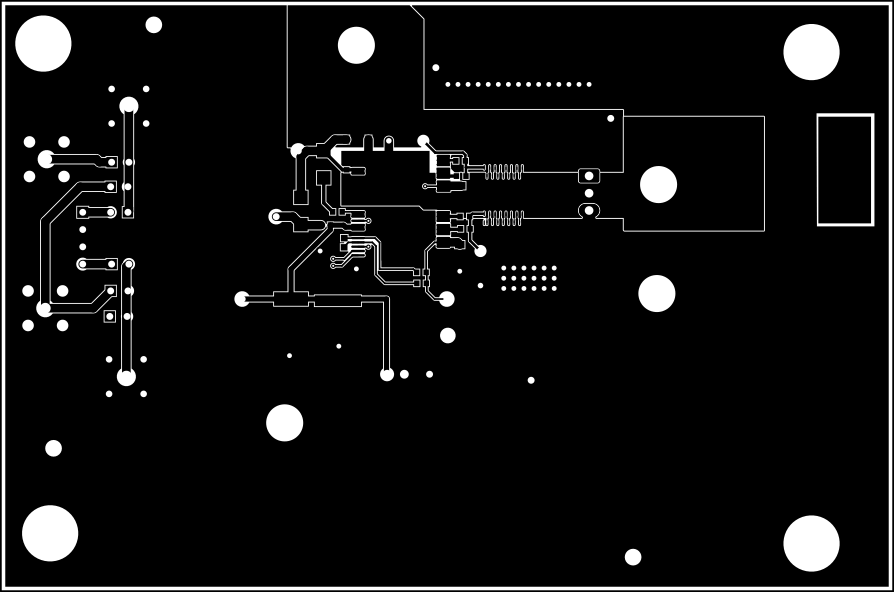 Figure 4-15 Top Layer (TPS7H6023EVM-CVAL)
 Figure 4-16 Signal Layer 1
(TPS7H60x3EVM-CVAL)
 Figure 4-17 Signal Layer 2
(TPS7H60x3EVM-CVAL)
 Figure 4-18 Signal Layer 3
(TPS7H60x3EVM-CVAL)
 Figure 4-19 Signal Layer 4
(TPS7H60x3EVM-CVAL)
 Figure 4-20 Signal Layer 5
(TPS7H60x3EVM-CVAL)
 Figure 4-21 Signal Layer 6
(TPS7H60x3EVM-CVAL)
 Figure 4-22 Bottom Layer
(TPS7H60x3EVM-CVAL)
 Figure 4-23 Bottom Overlay
(TPS7H60x3EVM-CVAL)
 Figure 4-24 Bottom Solder Mask
(TPS7H60x3EVM-CVAL)
 Figure 4-25 Board Dimensions
(TPS7H60x3EVM-CVAL)
 Figure 4-26 Top Solder (TPS7H6005EVM)
 Figure 4-27 Top Solder (TPS7H6015EVM)
 Figure 4-28 Top Solder (TPS7H6025EVM)
 Figure 4-29 Top Overlay (TPS7H6005EVM)
 Figure 4-30 Top Overlay (TPS7H6015EVM)
 Figure 4-31 Top Overlay (TPS7H6025EVM)
 Figure 4-32 Top Layer (TPS7H6005EVM)
 Figure 4-33 Top Layer (TPS7H6015EVM)
 Figure 4-34 Top Layer (TPS7H6025EVM)
 Figure 4-35 Signal Layer 1 (TPS7H60x5EVM)
 Figure 4-36 Signal Layer 2 (TPS7H60x5EVM)
 Figure 4-37 Signal Layer 3 (TPS7H60x5EVM)
 Figure 4-38 Signal Layer 4 (TPS7H60x5EVM)
 Figure 4-39 Signal Layer 5 (TPS7H60x5EVM)
 Figure 4-40 Signal Layer 6 (TPS7H60x5EVM)
 Figure 4-41 Bottom Layer
(TPS7H60x5EVM)
 Figure 4-42 Bottom Overlay
(TPS7H60x5EVM)
 Figure 4-43 Bottom Solder
(TPS7H60x5EVM)
 Figure 4-44 Drill Drawing
(TPS7H60x5EVM)