SLVUCN5B July   2023  – July 2024 TPS7H6003-SP


  1.   1
  2.   Description
  3.   Features
  4.   Applications
  5.   5
  6. 1Evaluation Module Overview
    1. 1.1 Introduction
    2. 1.2 Kit Contents
    3. 1.3 Specification
    4. 1.4 Device Information
  7. 2Hardware
    1. 2.1 Power Requirements
    2. 2.2 Best Practices
      1.      General Texas Instruments High Voltage Evaluation (TI HV EVM) User Safety Guidelines
  8. 3Implementation Results
    1. 3.1 Evaluation Setup
    2. 3.2 Performance Data and Results
  9. 4Hardware Design Files
    1. 4.1 Schematics
    2. 4.2 PCB Layouts
    3. 4.3 Bill of Materials (BOM)
  10. 5References
  11. 6Revision History

Performance Data and Results

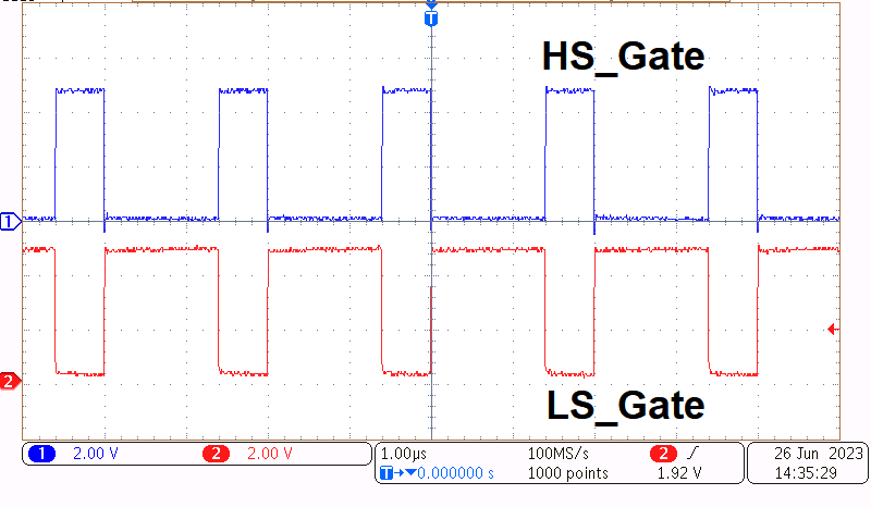
TPS7H6003EVM-CVAL, TPS7H6013EVM-CVAL, TPS7H6023EVM-CVAL, TPS7H6005EVM, TPS7H6015EVM, TPS7H6025EVM Gate Voltage of GaN FETs
Image shows gate voltage without phase node energized.
Figure 3-1 Gate Voltage of GaN FETs
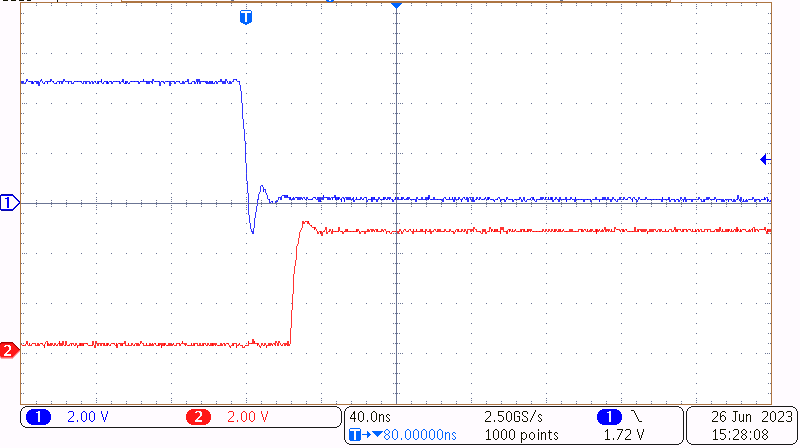
TPS7H6003EVM-CVAL, TPS7H6013EVM-CVAL, TPS7H6023EVM-CVAL, TPS7H6005EVM, TPS7H6015EVM, TPS7H6025EVM High to Low Transition of Gate
                    Voltage
Image shows gate voltage without phase node energized.
Figure 3-2 High to Low Transition of Gate Voltage
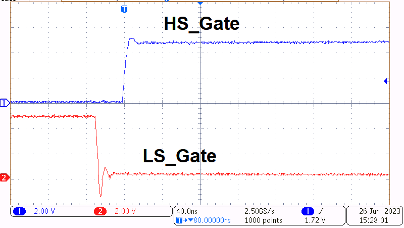
TPS7H6003EVM-CVAL, TPS7H6013EVM-CVAL, TPS7H6023EVM-CVAL, TPS7H6005EVM, TPS7H6015EVM, TPS7H6025EVM Low to High Transition of Gate Voltage
Image shows gate voltage without phase node energized.
Figure 3-3 Low to High Transition of Gate Voltage
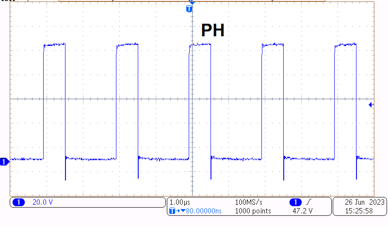
TPS7H6003EVM-CVAL, TPS7H6013EVM-CVAL, TPS7H6023EVM-CVAL, TPS7H6005EVM, TPS7H6015EVM, TPS7H6025EVM Phase Node Voltage Figure 3-4 Phase Node Voltage