SLVUCN6 February 2023 TPS274C65
6.1 Software Usage
Once you open the TPS274C65 Configurator software a connection to the EVM will automatically start to be initiated:
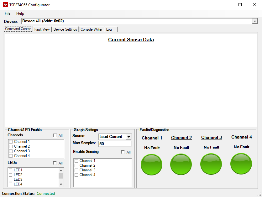 Figure 6-1 Configurator on
Startup
Figure 6-1 Configurator on
StartupThe configurator software will automatically detect when the EVM is plugged into or removed from the host system without any drivers. The connection status will automatically be indicated on the bottom of the task strip under the Connection Status label. If the software cannot find the EVM it will show as disconnected and all controls will be disabled:
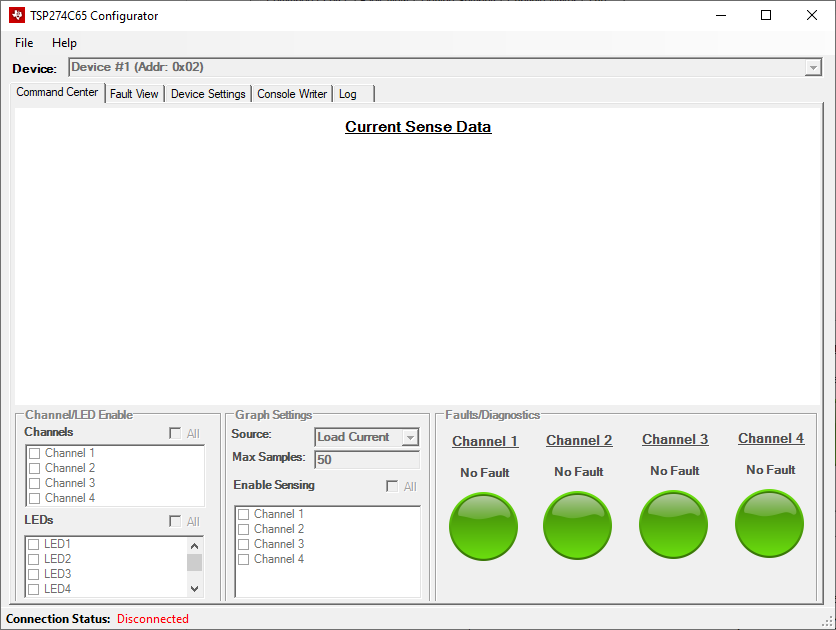 Figure 6-2 Disconnected Device
As the TPS274C65USBEVM contains two separate TPS274C65 high-side switches, the Device selector combo box on the top of the screen is used to switch views between the two devices. When switching between devices, all information on the current screen is automatically read from the register map of the device without the need for any manual interaction. There are two devices on the TPS274C65EVM:
- Device #1 (Addr: 0x02)
- Device #2 (Addr: 0x05)
The device's address are configured using the resistors on R26 and R35 of the EVM. If the user wishes to change the address of the device, these resistors must be changed on the EVM in accordance to the datasheet parameters.
To turn on and off channels for the high-side switch, simply check the boxes under the Channels group. Whenever a single box is checked, the program will communicate with the MCU on the EVM to turn on the selected channel. The MCU will automatically construct the relevant SPI packet and send it to the high-side switch. Similarly, clicking any of the boxes under the LEDs group will toggle the LEDs connected to the TPS274C65's debug LED outputs.
To enable real-time sensing/graphing of the TPS274C65's integrated ADC results, the user should enable sensing by checking any of the Channel boxes under Enable Sensing. This will start a polling thread in the background to periodically sample and read the results of the ADC_RESULT registers in the TPS274C65. Note that by enabling sensing, the device automatically enables the ADC_EN bit of the DEV_CONFIG5 register of the selected device so that relevant data can be read. The user can choose to graph the following different sources via the Source combo box:
- Load current
- FET Temperature
- Output Voltage
Note that when sensing is enabled, input voltage will automatically be displayed on the task strip at the bottom of the window. Additionally, the numerical value of the current sample will be displayed below the Channel label in the Faults/Diagnostics group when sensing is enabled. An example of a light load current being graphed can be seen below:
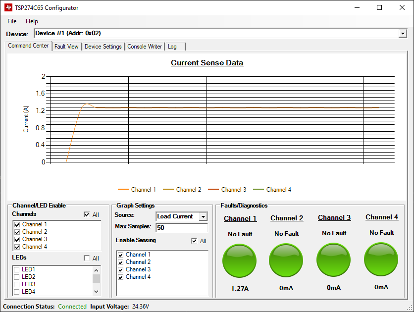 Figure 6-3 Light Load Current
The maximum number of samples that are collected/stored on the graph can be adjusted via the Max Samples box.
The Fault/Diagnostics group shows a high-level representation of the per-channel fault status. Specifically, these fault statuses mirror the values in the FAULT_CH_STAT register of the device. A background thread is running that automatically updates the graphic representations. If a fault exists in the system the indicator turns red and if no fault exists the indicator is green. An example of a faulted channel (in this case current limit) can be seen below:
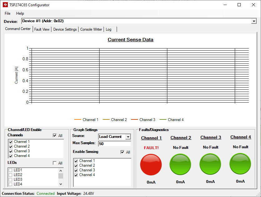 Figure 6-4 Faulted Channel
Note that if you click the fault icon the navigation will automatically change to the detailed Fault View:
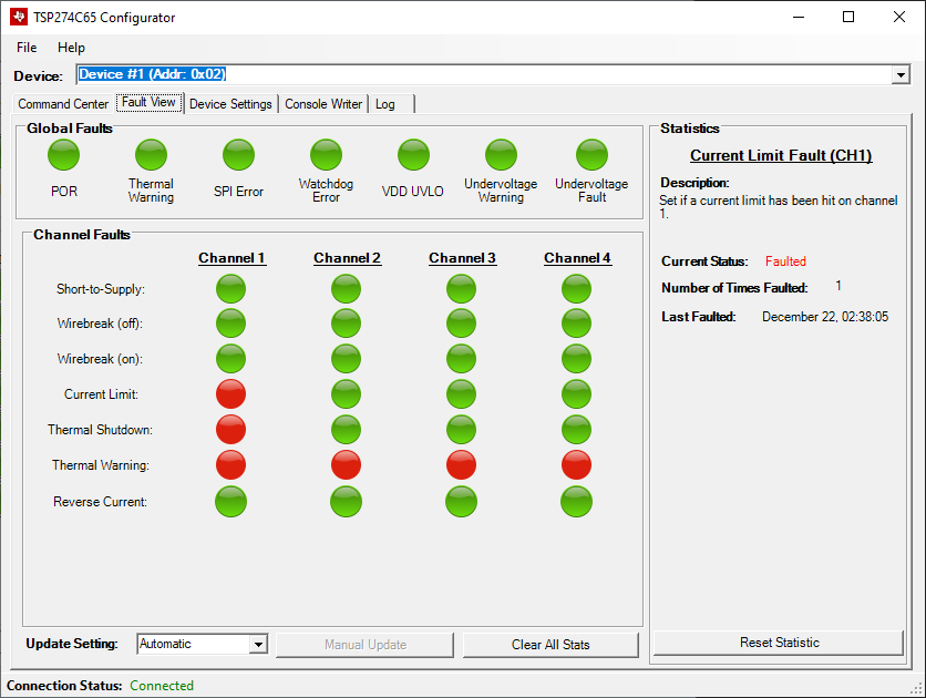 Figure 6-5 Fault View
The fault view of the device contains a detailed report of each fault in the system on both a global level and a per-channel level. This view simply aggregates the following registers from the TPS274C65's register map:
- FAULT_TYPE_STAT (represented in Global Faults)
- SHRT_VS_CH_STAT (Short-to-Supply)
- WB_OFF_CH_STAT (Wirebreak (off))
- WB_ON_CH_STAT (Wirebreak (on))
- ILIMIT_CH_STAT (Current Limit)
- THERMAL_SD_CH_STAT (Thermal Shutdown)
- THERMAL_WRN_CH_STAT (Thermal Warning)
- RVRS_BLK_CH_STAT (Reverse Current)
For detailed descriptions of all of these faults and what they indicate, refer to the TPS274C65 datasheet. Note that when you click any of the fault indicator icons the Statistics pane is updated on the right of the window to reflect the selected fault. In the statistics view, the user is able to see how many times the specific fault occurred as well as when the fault last occurred. To reset the local statistic data, the user can either click Reset Statistic to reset the individual statistic or Clear all Stats to reset all of the local statistics.
For many of the faults (such as POR), reading the fault status will clear the bit in the fault status register. Because of this, the user has the ability to switch between Manual and Automatic update mode. In automatic mode, a background task automatically polls the high-side switch's fault registers and reports the fault status via the fault view. To switch to manual mode, change the Update Setting combo box to Manual. This will enable the Manual Update button. When this button is clicked all statistics for the selected TPS274C65 device are updated manually.
The next tab controls all of the settings of the device.
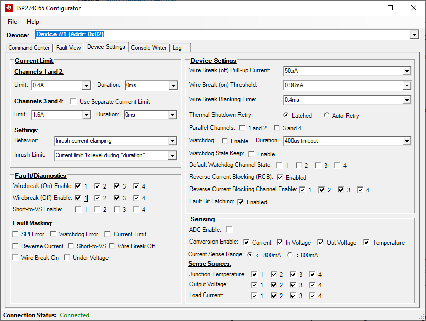 Figure 6-6 Device Settings
For the specific meaning of each one these settings, please refer to the TPS274C65 datasheet. Specifically, each setting closely mirrors the register map settings of the device. It is important to note that some settings will not be able to be changed when the device has channels actively enabled. When a channel is enabled, the affected settings will be grayed out to prevent interaction from the use. The controls on the device settings page are active. This means that as soon as you change a value, the relevant change will be persisted to the microcontroller and to the high-side switch.
The Console Writer tab gives the user the ability to perform direct read/write operations to the selected TPS274C65.
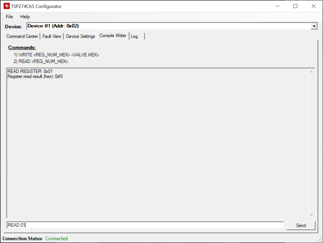 Figure 6-7 Register Read
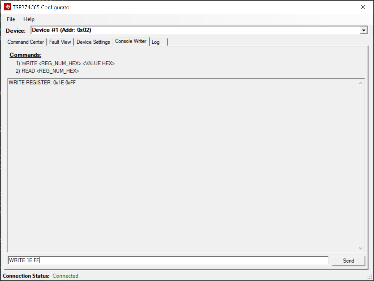 Figure 6-8 Register Write
This provides a direct way to manipulate the bitwise settings of the TPS274C65's register map without any interaction with functional controls. Examples on how to read/write directly to the high-side switch's register maps can be seen in the screenshots above.
The last tab of the application is the device log. This tab simply keeps a timestamped record of all events that have happened on the configurator tool.
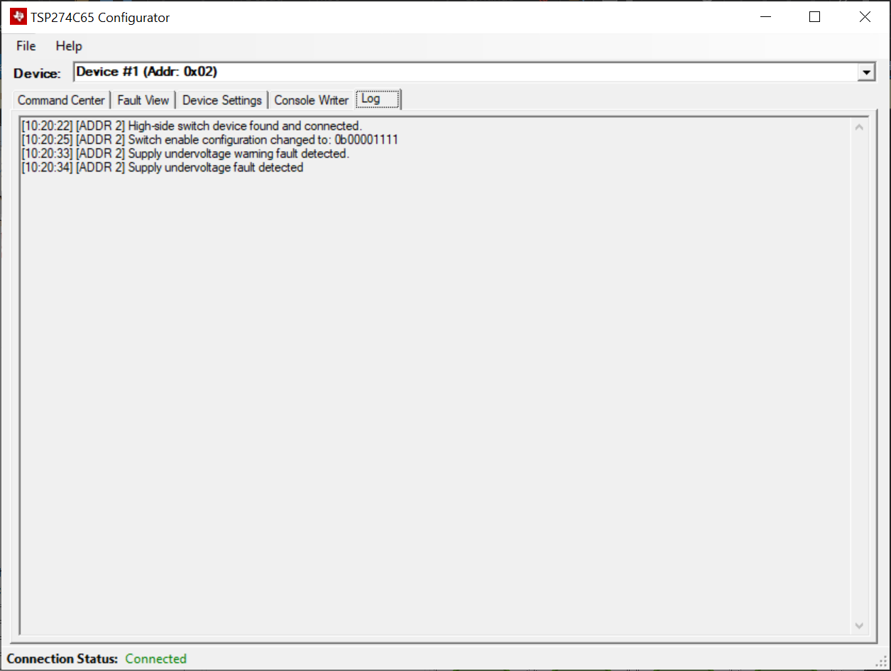 Figure 6-9 Device Log
Another feature that the TPS274C65 Configurator tool has is the ability to save/load configurations. This allows the user to export/import all of the configured settings of the device for ease-of-use. Note that this functionality is only available when the TPS274C65USB EVM is connected. To access this feature, simply click the relevant function on the File menu. The exported configuration file is a simple ASCII text file with the configuration of both high-side switches on the board.