SLVUCN9 September 2023 TPSM365R15
4 Schematic
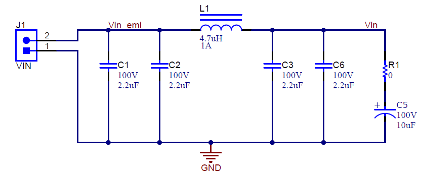
Customers can choose to implement a PI filter in series with the input of a power regulator, which allows for the differential noise generated to be attenuated, allowing a noise emission regulation to be met. The filter crossover frequency is designed for 1-MHz switching frequency, attenuating the switching frequency and the corresponding harmonics greatly. A damping capacitor is provided (C5), to damp the high-Q, PI filter. For more information on filter damping, see Section 8.
 Figure 4-1 Schematic-Compliance Testing Filter
In the buck schematic, the difference between the TPSM365R15EVM and TPSM365R15FEVM is the REFDES=U1 device part number, with pin definition RT (adjustable frequency) or Mode/Sync (mode select or synchronization) differing. Additional feedback resistors are provided to program the different, possible output voltages and placeholders are supplied for additional output capacitance to achieve stability or meet a output transient specification.
 Figure 4-2 Schematic (TPSM365R15EVM) – TPSM365R15
 Figure 4-3 Schematic (TPSM365R15EVM) – Configuration Jumpers and Evaluation Test Points
A disable, frequency select, and output voltage select jumper are provided to aid the evaluation. Additionally, test points to evaluate product features and stability are provided.
The TPSM365R15RDNR can be configured for a fixed 3.3-V output by populating R11. Remove R10 to make sure of an accurate IQ measurement for a fixed 3.3-V output.
 Figure 4-4 Schematic (TPSM365R15FEVM) – TPSM365R15F
 Figure 4-5 Schematic (TPSM365R15FEVM) – Configuration Jumpers and Evaluation Test Points
A disable, mode select or synchronization, and output voltage select jumper are provided to aid the evaluation. Additionally, test points to evaluate product features and stability are provided.
The TPSM365R15FRDNR can be configured for a fixed 5-V output by populating R11. Remove R10 to make sure of an accurate IQ measurement for a fixed 5-V output.