SLVUCO1A May 2023 – April 2024 DRV8213 , DRV8214 , DRV8234
PRODUCTION DATA
3.6.1 Quick Start
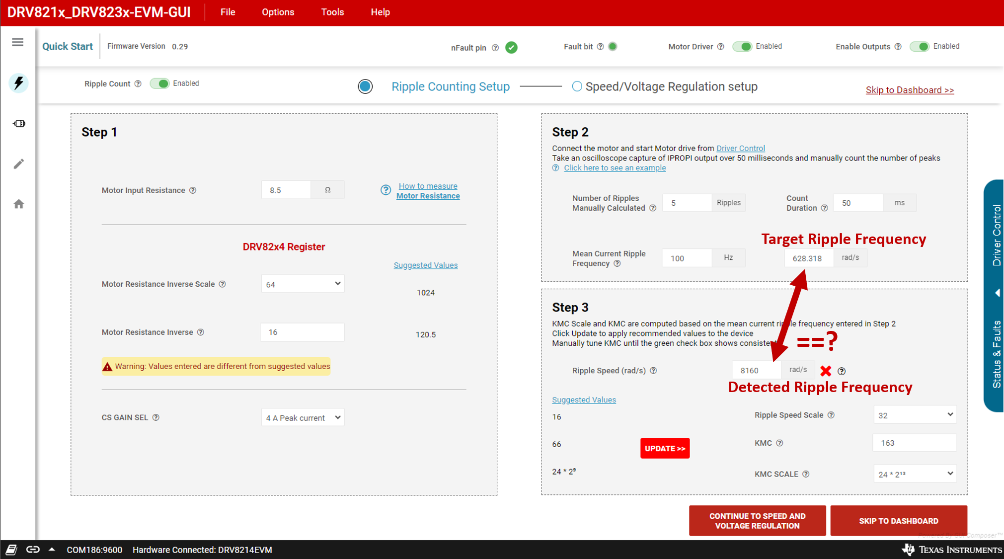
 Figure 3-8 Quick Start Page - Ripple
Counting Setup
Figure 3-8 Quick Start Page - Ripple
Counting SetupThe Quick Start page gives a three-step process to tune the device parameters with your motor. This is applicable for all four of these EVMs (not DRV8213), even DRV8215/DRV8235 which do not have RC_OUT. The steps to follow are the same between all four devices.
Step 1 - Motor Resistance and Current
- Input the motor resistance into the first box. Click How to measure motor resistance for a few ways to determine the resistance of the motor if not given in the motor data sheet.
- The Suggested Values for Motor Resistance Inverse Scale (INV_R_SCALE) and Motor Resistance Inverse automatically updates. Use the corresponding drop-down and input box to apply these suggested values to the device registers. Once the values are near the suggested values, the warning goes away.
- Select an appropriate CS GAIN SEL for the motor (DRV8214/DRV8215 only). This scales the output of IPROPI, and help achieve maximum accuracy. DRV8234/DRV8235 have a single set value for CS GAIN SEL, so this drop-down is disabled in those GUI variants.
Step 2 - Ripple Frequency
- Use the Driver Control Panel to start spinning the motor at 100% duty cycle with no load. The motor must be spinning for the reminder of the tuning steps.
- Attach an oscilloscope or logic analyzer to the IPROPI test point on the EVM, or clamp a current probe around a motor lead.
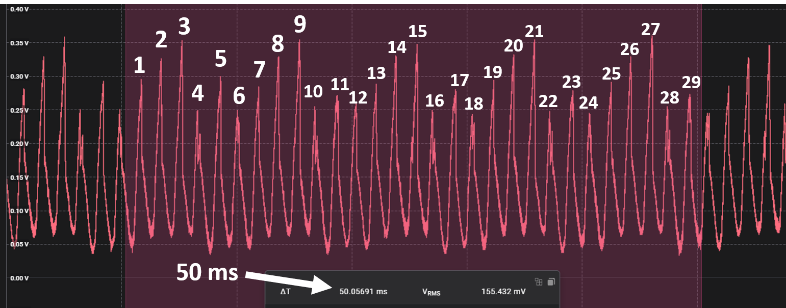
- Capture at least 50 milliseconds of current
waveform. Count the number of peaks as shown in Figure 4-9. Input the number of peaks into the Number of Ripples Manually
Calculated box, and enter the capture time (ex. 50ms) into the Count
Duration box. TI recommends counting at least 20 ripples for a given motor.
 Figure 3-9 Electrical Ripple
Speed Measurement
 - The Mean Current Ripple Frequency boxes
automatically updates to convert this ripple count into Hz and rad/s. The value
displayed in the rad/s box is the value to tune the device to measure and match
in Step 3. Note that this is an electrical speed, not a mechanical speed. The
mechanical motor RPM can be calculated with Equation 1..
Step 3 - Parameter Tuning
The Ripple Speed (rad/s) box in Step 3 displays the ripple speed value last detected by the motor driver. The goal of Step 3 is to adjust KMC, KMC_SCALE, and Ripple Speed Scale until the ripple speed detected by the device matches the target ripple frequency in Step 2. When the detected speed is within 2*Ripple_Speed_Scale of the target speed then a green check box appears.
The Suggested Values on the left automatically updates based on the device ripple speed box following the steps outlined in the data sheet to tune these parameters to match the target ripple frequency. Clicking the UPDATE>> button automatically applies all the suggested values to the device register. Alternatively, the user can use the drop-down options and input box to manually adjust these.
- With the motor spinning, click the UPDATE>> button to apply the suggested values to the register.
- Wait a few seconds for the detected Ripple Speed in step 3 to update, and if the Ripple Speed does not match, then press the Update button again.
- Repeat step 2 until the green check box is
continuously showing, indicating the detected ripple speed closely matches the
target speed.
- Overflow conditions can cause this algorithm to get stuck on the KMC_SCALE of 24 * 213. If this happens, then use the KMC SCALE drop-down to select 24 * 212 or 24 * 29.
- The Ripple Speed Scale is computed to give the maximum resolution of motor speed for the speed scale. However, if the target speed is very close to the maximum ripple speed of that scale (255 * Ripple Speed Scale. For example, 255 * 16 = 4080), then the user needs to increase ripple speed scale to the next value.
- A higher value of KMC results in a lower detected ripple speed, and vice versa. So if the target speed is 3000 rad/s and the device is reading 4000 rad/s at a given KMC_SCALE, then try increasing KMC.
- If the automatic update method is not working
well for the motor, then manually adjust KMC and KMC_SCALE.
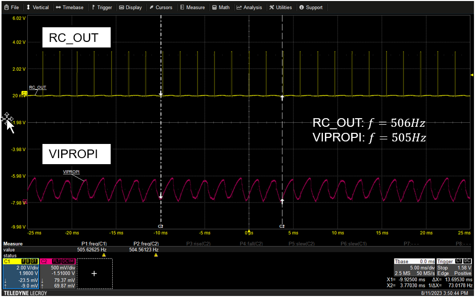
- Start with the lowest KMC_SCALE value and setting KMC to 255. If the detected ripple frequency is lower than the target ripple frequency, then move to the next KMC_SCALE and repeat the process until the detected frequency is higher than the target ripple frequency. At this point, choose the previous KMC_SCALE (for example, if ripple frequency becomes higher than target ripple frequency with KMC_SCALE=24*212, select KV_SCALE=24*29). Then, decrease KMC value from 255 until RC_OUT frequency matches with the current ripple frequency. The figure below shows RC_OUT and current ripple waveforms for correct tuned parameters. The RC_OUT and current ripple frequency is around the same value. There can be slight differences on variations in the frequencies of both signals, as long as the frequency is within an acceptable margin.
There is likely two combinations of KMC and KMC_SCALE that work for a given motor. In this case, pick the combination with the larger KMC value, this gives the tracking better resolution. For example, if the combinations [24*28 with KMC=82] or [24*29 with KMC=168] or both work, then select the second option since KMC is larger.
 Figure 3-10 IPROPI and RC_OUT waveform
after parameter tuning
 Figure 3-11 Quick Start Page -
Speed/Voltage Regulation Setup
Figure 3-11 Quick Start Page -
Speed/Voltage Regulation SetupStep 1 - Regulation Type
The REG_CTRL drop-down changes the REG_CTRL register to the selected entry. Note that this can only be selected when outputs are disabled, so toggle the top right "Enable Outputs" toggle to off before changing these settings.
Step 2 - Regulation Target
Use the Target Speed and Target Voltage boxes to input the target parameter for the regulation mode if in speed/voltage regulation. The user can press the Set Max button to set them to the max value.
Step 3- Soft Start/Stop
Use the Soft Start/STop toggle to enable or disable this feature. Put the duration for soft start or soft stop in the input box with a unit of milliseconds. This updates the TINRUSH register.
Step 4 - Advanced - PI Parameters
This box can be used to adjust the KP, KP_DIV, KI, and KI_DIV parameters if needed. These rarely need to be adjusted, and the device tweaks these as the device functions as part of the control loop with the motor. TI does not recommended to change these under typical circumstances.