SLVUCP5 june   2023 TPSM828510 , TPSM828511 , TPSM828512


  1.   1
  2.   Description
  3.   Get Started
  4.   Features
  5.   Applications
  6.   6
  7. 1Evaluation Module Overview
    1. 1.1 Introduction
    2. 1.2 Kit Contents
    3. 1.3 Performance Specifications
    4. 1.4 Device Information
  8. 2Hardware
    1. 2.1 Setup
      1. 2.1.1 Connector Descriptions
      2. 2.1.2 Hardware Setup
    2. 2.2 Modifications
      1. 2.2.1 Input and Output Capacitors
      2. 2.2.2 Adjustable-Output IC U1 Operation
      3. 2.2.3 Feedforward Capacitor
      4. 2.2.4 Soft-Start Time
  9. 3Implementation Results
    1. 3.1 TPSM82851xEVM Test Results
  10. 4Hardware Design Files
    1. 4.1 Schematic
    2. 4.2 PCB Layouts
    3. 4.3 Bill of Materials
  11. 5Additional Information
    1.     Trademarks

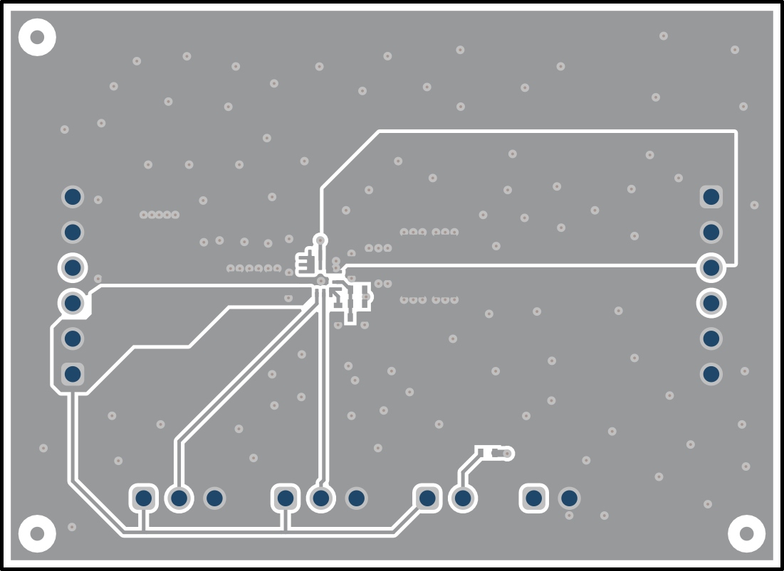
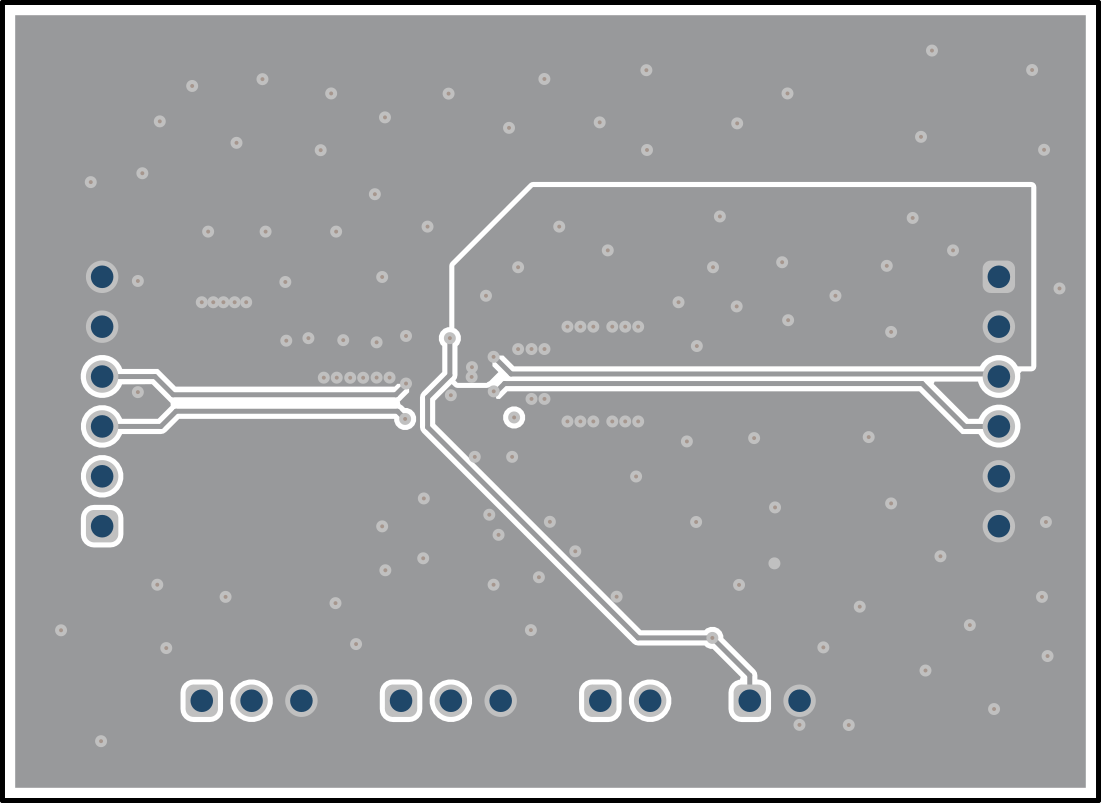
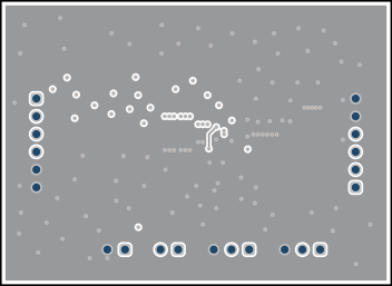
PCB Layouts

This section provides the TPSM82851xEVM board layout. See the TPSM82851xEVM tool page for more details.

GUID-20230515-SS0I-FXT7-LBJ4-JHJM5DVMBFDL-low.svgFigure 4-2 Top Silk
GUID-20230515-SS0I-MQXB-SLFS-CXH8QCJ6V4JD-low.pngFigure 4-3 Top Layer
GUID-20230515-SS0I-RR9N-1RGL-8SLVVTLMXN53-low.svgFigure 4-4 Layer 2
GUID-20230515-SS0I-SDZ8-TC8H-KJTWFBPXVFNX-low.pngFigure 4-5 Layer 3
GUID-20230515-SS0I-NLD5-SG2J-NZXQTMVHKWB8-low.pngFigure 4-6 Bottom Layer