SLVUCS1A july   2023  – august 2023 TPS7H2140-SEP
 

  1.   1
  2.   Description
  3.   Features
  4.   4
  5. 1Evaluation Module Overview
    1. 1.1 Introduction
    2. 1.2 Kit Contents
    3. 1.3 Specification
    4. 1.4 Device Information
  6. 2Hardware
    1. 2.1 Connection Descriptions
      1. 2.1.1 Connectors
    2. 2.2 Variable Resistors for CS and CL
      1. 2.2.1 Current Sense Resistor
      2. 2.2.2 Current Limit Resistors
    3. 2.3 Open-Load Detection Pull-Up Resistors
    4. 2.4 Connecting Channels In Parallel
  7. 3Implementation Results
    1. 3.1 Separated Output Results
      1. 3.1.1 Power Up and Power Down
      2. 3.1.2 Enable and Disable
      3. 3.1.3 Current Sensing
      4. 3.1.4 Load Step Effects Across Output Channels
      5. 3.1.5 Overcurrent Protection
    2. 3.2 Modified Configuration Results
      1. 3.2.1 Short-to-GND (Fast-Trip) Overcurrent
  8. 4Hardware Design Files
    1. 4.1 Schematic
    2. 4.2 PCB Layouts
    3. 4.3 Bill of Materials
  9. 5Additional Information
    1.     Trademarks
  10. 6Related Documentation
  11. 7Revision History

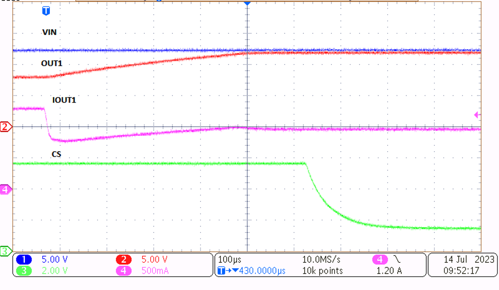
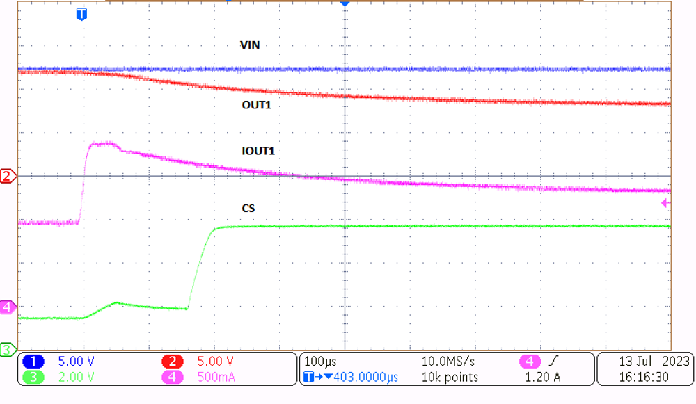
Overcurrent Protection

GUID-20230717-SS0I-MH5Z-GQVF-CDDM7HBJPH39-low.pngFigure 3-7 OCP Assertion at RLoad = 6 Ω
GUID-20230717-SS0I-CSPF-JV9M-TS1KF51CBC2C-low.pngFigure 3-8 OCP Deassertion by returning RLoad = 12 Ω

Both tests were performed using VIN = 12 V, and a load between 6 Ω and 12 Ω.