SLVUD20 October   2024 DRV8376


  1.   1
  2.   Description
  3.   Get Started
  4.   Features
  5.   Applications
  6.   6
  7. 1Evaluation Module Overview
    1. 1.1 Introduction
    2. 1.2 Kit Contents
    3. 1.3 Specification
    4. 1.4 Device Information
  8. 2Hardware
    1. 2.1 Quick Start
    2. 2.2 LaunchXL-F280049C Setup
    3. 2.3 LED Indicators
    4. 2.4 Jumper Information
    5. 2.5 Test Points
    6. 2.6 Hardware Variant Configuration
    7. 2.7 SPI Variant Configuration
    8. 2.8 MCx Variant Configuration
  9. 3Software
    1. 3.1 DRV8376EVM GUI Software
  10. 4Hardware Design Files
    1. 4.1 Schematics
    2. 4.2 PCB Layouts
    3. 4.3 Bill of Materials (BOM)
  11. 5Additional Information
    1. 5.1 Trademarks

LED Indicators

The DRV8376EVM has a few LEDS on the board that indicate the status of the board.

All the LED indicators that are present on the DRV8376EVM are shown in Figure 2-3.
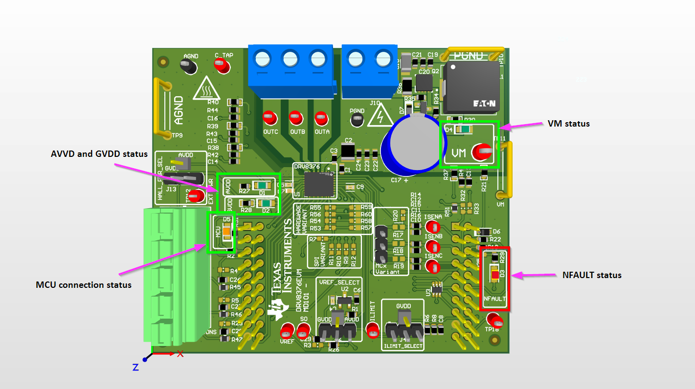
DRV8376EVM DRV8376EVM LED
                    Indicators Figure 2-3 DRV8376EVM LED Indicators

These LEDs need to be monitored throughout the use of the DRV8376EVM. The status LEDs for VM, AVDD, and GVDD turn on once power is supplied to the board. The MCU LED turns on once the GUI or Firmware runs on the LaunchXL-F280049C while the DRV8376EVM is connected. The NFAULT status LED turns on as soon as a driver fault occurs.