SLWU087E november 2013 – june 2023
- 1
- High Speed Data Converter Pro GUI
- Trademarks
- 1 Introduction
- 2 Software Start up
-
3 User Interface
- 3.1
Toolbar
- 3.1.1 File Options
- 3.1.2 Instrument Options
- 3.1.3 Data Capture Option
- 3.1.4
Test Options
- 3.1.4.1 Notch Frequency Bins
- 3.1.4.2 2 Channel Display and Cursor Lock
- 3.1.4.3 Analysis Window Markers
- 3.1.4.4 X-Scale in Time
- 3.1.4.5 Y-Scale in Voltage
- 3.1.4.6 Other Frequency Options
- 3.1.4.7 NSD Marker
- 3.1.4.8 Phase Plot
- 3.1.4.9 Phase in Degree
- 3.1.4.10 Histogram
- 3.1.4.11 Disable User Popups
- 3.1.4.12 HSDC Pro Lite Version
- 3.1.5 Help
- 3.2 Status Windows
- 3.3 Mode Selection
- 3.4 Device Selection
- 3.5 Skip Configuration
- 3.6 Capture Button (ADC Mode Only)
- 3.7 Test Selection (ADC Mode only)
- 3.8 DAC Display Panel (DAC Mode only)
- 3.9 I/Q Multi-Tone Generator
- 3.1
Toolbar
- 4 ADC Data Capture Software Operation
- 5 TSW1400 Pattern Generator Operation
- 6 TSW14J58 Functional Description
- 7 TSW14J57 Functional Description
- 8 TSW14J56 Functional Description
- 9 TSW14J50 Functional Description
- 10TSW14J10 Functional Description
- A Signal Processing in High Speed Data Converter Pro
- B History Notes
- C Revision History
2.2 USB Interface and Drivers
The HSDC Pro GUI will first attempt to connect to the EVM USB interface. If the GUI identifies a valid board serial number, a pop-up will open displaying this value, as shown in Figure 2-1. The serial number also has an EVM type number attached to it. This indicates to the GUI which TSW14xxx board is presently connected to the host PC. It is possible to connect several TSW14xxx EVMs to one host PC but the GUI can only connect to one at a time. If multiple boards are connected to the PC, the pop-up displays all of the serial numbers found. It is then up to the user to select which board the GUI is associated.
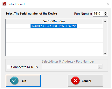 Figure 2-1 TSW14xxx EVM Serial Number
Port Number in the above pop up is used to launch the TSW Controller App in the specified port number or to connect to an already opened instance. TSW Controller App gets installed along with HSDC Pro from version 6.0 onwards. TSW14J59 EVM communication with HSDC Pro happens through this app. This app is launched in a hidden state by default. To unhide the tool change TSW_Controller Hidden value to FALSE in TSW_Controller Details.ini, located in C:\Program Files\Texas Instruments\High Speed Data Converter Pro.
Click on “OK” to connect the GUI to the board. Now the GUI prompts the user as shown in Figure 2-2 to select the type of EVM that is to be tested with the TSW14xx EVM (either ADC, DAC, or AFE) from the Supported Device list. Select an option to proceed further.
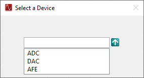 Figure 2-2 Select Device
After connecting to the board, if the FPGA firmware version read by the GUI does not match the firmware to be used as determined by the device selected (see Device Selection for more info on device selection), the following message appears as shown in Figure 2-3. This message also appears after power up as the FPGA is not programmed.
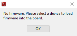 Figure 2-3 Firmware Does Not Match the Device Selected
Click on “OK”. The Top level GUI now opens and appears as shown in Figure 2-4.
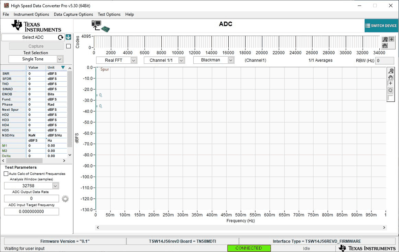 Figure 2-4 TSW14xxx EVM GUI Top Level
After the software has established a connection, if the message “No Board Connected” opens, double check the USB cable connections and that power is present. If the cable connections appear fine, try establishing a connection by clicking on the “Instrument Options” tab at the top left of the GUI and select “Connect to the Board” (see Figure 2-5). If this does not help, disconnect the USB cable from the board then reconnect it, click on the "Instrument Options" tab, then select "Connect to the Board". If this still does not correct the issue, check the status of the host USB port.
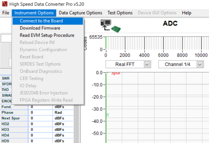 Figure 2-5 Connecting GUI to EVM
When the software has been installed and the USB cable has been connected to a TSW1400EVM and the PC, the USB serial converter should be located in the Hardware Device Manager under the Universal Serial Bus controllers as shown in Figure 2-6. This is a quad device which is why there is an A, B, C, and D USB Serial Converter shown. When the USB cable is removed, these four will no longer be visible in the Device Manager. If the drivers are present in the Device Manager window and the software still does not connect, cycle power to the board and repeat the steps above.
If the GUI starts up but freezes before it brings up the "Connected to Board" dialog, or takes an unusually long time for other actions to occur, it is possible the USB being used from the host PC is operating at USB 1.0 speeds. A common indication of this is when the status bar on the bottom left of the screen keeps reading "Disable all Controls" upon loading the software without ever going to the "Connect Board Dialog". The GUI is designed to run at USB 3.0 speeds and some computers have USB 1.0 ports on the front panel and 2.0 or 3.0 on the back panel. Using the 3.0 ports on the back of the PC if at all possible is recommended.
The .exe file installs the FTDI drivers during software installation. If after connecting the USB cable and Windows lists the board as an "unknown device", this could be caused by corrupted FTDI drivers being installed on the computer. This happens in cases where the same computer has been used to interface with previous products that used FTDI drivers. In this case, users are advised to download and install a utility from FTDI at:
http://www.ftdichip.com/Support/Utilities/CDMUninstaller_v1.4.zip
The help file for using this utility is found at:
http://www.ftdichip.com/Support/Utilities/CDM_Uninst_GUI_Readme.html
Use the following hex values to uninstall previous versions of the ftdi drivers:
Vendor ID (VID): 0403
Product ID (PID): 6010
After removing the drivers for this PID and VID, users are advised to re-connect the TSW14xxx USB cable and check if the TSW14xxx ports get listed properly in Device Manager.
For the TSW14J5x, the .exe file installs the Cypress USB 3.0 drivers during software installation. The USB 3.0 driver, called "Cypress FX3 USB StreamerExample Device", is located in the Hardware Device Manager under the Universal Serial Bus controllers as shown in Figure 2-7.
If Windows lists the board as an "unknown device" after connecting the USB cable, this may be caused by the Cypress USB 3.0 not booting properly from the flash device. Press the USB reset switch SW11 (SW5 on J57), and try to reconnect the GUI. If this does not work, cycle the board power.
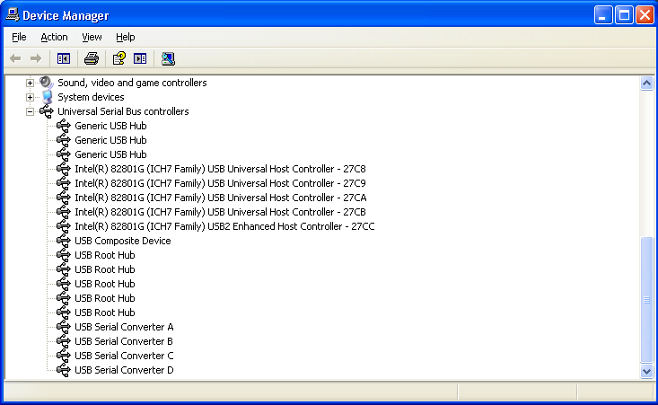 Figure 2-6 Hardware Device Manager
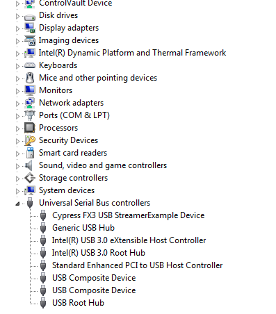 Figure 2-7 Cypress FX3 USB Streamer Example Device in USB Controllers