SLYA058 June 2022 DRV5021 , DRV5032 , DRV5033 , TMAG5123 , TMAG5124 , TMAG5170 , TMAG5273 , TMAG5328
2.1 Switch Implementation
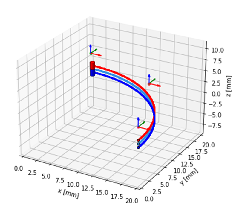
One way to detect the position of a deadbolt using switches is by having a magnet rotate around the center shaft. From this, you can have Hall-effect switches placed to determine when the deadbolt is in the unlocked position and locked position. These switches can also be placed to determine if the lock is installed on a right-handed door or left-handed door.
 Figure 2-1 Hall-Effect Switch
Implementation Example
Figure 2-1 Hall-Effect Switch
Implementation ExampleIn this example, there are three switches to determine the position of the deadbolt rotation as the magnet sweeps around the center shaft. The center switch can be used to determine when the deadbolt is completely open and the two end switches can be used to determine when the deadbolt is completely closed, one for a left-handed door installation and one for a right-handed door installation. This way, the lock can be installed on any door and still detect the position of the deadbolt. Figure 2-2 shows an example of the magnetic field of the magnet as it moves along this path and the digital output of the switches. The Bz1, Bz2, and Bz3 lines are the magnetic field strengths at each sensor while the D1, D2, and D3 lines are the digital outputs based on the sensors Bop. The device hysteresis due to the smaller Brp of the device is not accounted for in this graph so this only shows when the switches will turn on in either direction.
This simulation assumes the use of the DRV5032FB which has a typical magnetic threshold of 3 mT. The sensor is placed 2 mm away from the end of the magnet which yields a 12-mT peak in the sensed magnetic field. The mechanical tolerance of each switch can be adjusted by changing the distance between the magnet and sensor or by using a device with a different threshold. By increasing the distance, Figure 2-3 shows a tighter tolerance for when the switches detect the magnet.
While this implementation only uses three switches, adding switches or changing their placement will give more information about the position of the deadbolt. The magnet used for the above simulations is an N52 bar magnet with a 1/16th inch diameter and one-eighth inch thick. If a larger magnet is used, the magnetic field strength can be increased to allow the switches to turn on sooner for the rotational motion. For example, a similar bar magnet with a one-fourth inch thickness with a 2-mm gap between the end of the magnet and the sensor yields the following.
The new peak magnetic field is roughly 13.3 mT. This increase is not very large but also gives a wider angle range of when the sensor output is triggered. Selecting a magnet for this application can rely heavily on the space available in the system but factors like desired tolerance should be considered and compared to the magnet threshold of the sensor.
Using a Hall switch is a low power and low-cost implementation. The previously mentioned DRV5032FB can operate on less than 1 µA to preserve battery life in this application. Hall sensors also provide additional product lifetime when compared to reed switches. For more details on a comparison between reed switches and Hall sensors, see the Reed Switch Replacement with TI's Hall-effect and Linear 3D Hall-effect Sensors application note.