SLYA059B July 2022 – May 2024 TMAG5170 , TMAG5170-Q1 , TMAG5170D-Q1 , TMAG5173-Q1 , TMAG5273
1 Introduction
When detecting the linear motion of a magnet in any system, designers must maximize the total sensing range of the sensor for a particular magnet in use while maintaining a tight tolerance on overall measured position error. This strategy allows the designer to minimize the size of the magnet and reduce the total number of Hall-effect sensors needed in an array to capture the full stroke length of the system.
Tighter tolerances for magnetic position sensing produce improved feedback in controlled systems like linear motor transport systems by providing exact locations for each individual mover in the system. In linear motor transport systems, there are typically several individual movers that drive around a track or platform using repeating linear motors. For any mover, understanding absolute position at all times is important to properly place the target at each manufacturing step, to efficiently move the platforms for maximum throughput, and to accurately drive the motor stage controlling that position.
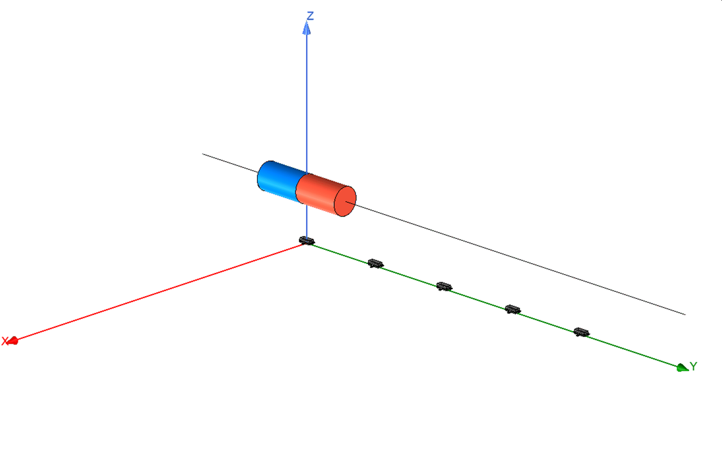
Traditionally, this function has been supported by one-dimensional linear Hall-effect sensors, such as the DRV5055 which capture the z-component of the magnetic field when using the SOT-23 package.
 Figure 1-1 Linear Position Sense Array With One-Dimensional Hall-Effect Sensors
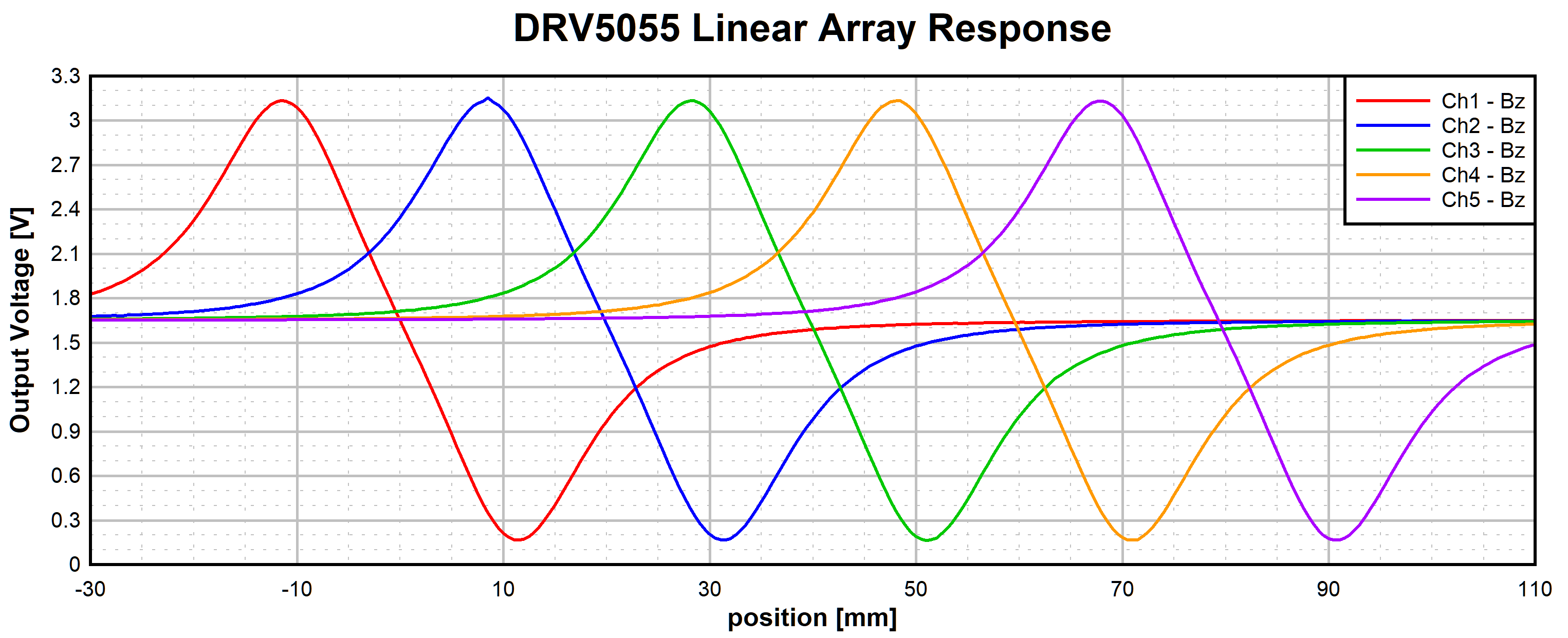
In this style of position-sensing configuration, the sensing range is limited to a linear region of the input magnetic field which is approximately the length of the magnet.
 Figure 1-2 DRV5055 Output in Linear Array Configuration
This configuration is described in more detail in Linear Hall Effect Sensor Array Design, application note.
There are significant advantages gained by implementing this design using a 3D linear Hall-effect sensor like the TMAG5170, TMAG5173-Q1, or TMAG5273. Firstly, the sensors are capable of detecting each component of the complete B-field vector. With expanded information, we can identify exact magnet position over a range of motion longer stroke lengths than can be detected using a single axis sensor. Additionally, these sensors have integrated functions for amplitude and offset correction which are useful for correcting various electro-mechanical factors.
 Figure 1-3 Example Magnetic Field Components Observed During Linear Motion
Examine how the selection of a magnet can impact the quality of the position measurement in a slide-by arrangement using a 3D sensor, and how to best linearize this measurement for minimal error.