SLYA060 August 2022 TMAG5110 , TMAG5110-Q1 , TMAG5111 , TMAG5111-Q1
2 System Block Diagram
To showcase magnetic incremental wheel encoding, the TI-RSLK robotic kit was used and modified for this design. This kit includes the following:
Robot chassis with two wheels and one ball caster
Chassis board that includes DRV8838 motor drivers, connection headers to an external LaunchPad™ development kit, and power management circuits
Two gear motors each with their own encoder assembly
Bumper switch assembly (not used in design)
Sensors for detecting changes in reflectance on the ground (not used in design)
The encoder board that comes with the kit uses two 1D latches to detect wheel speed and direction. For magnetic encoder testing, a new version of this board was created to use one TMAG511x 2D latch per encoder instead of two 1D latches. The board can support either the TMAG5110 or TMAG5111. If the TMAG5110 is used, two independent outputs are produced, which provides more resolution than one independent output. If the TMAG5111 is used, there are dedicated speed and direction outputs, which simplifies determining the direction at which the motor shaft is rotating (clockwise or counterclockwise).
The optical encoder testing was done using another board, which includes an IR emitter and phototransistor. A code disc was 3D printed to fit on the motor shaft so that it would alternate between allowing and blocking the light beam sent from the IR emitter to the phototransistor.
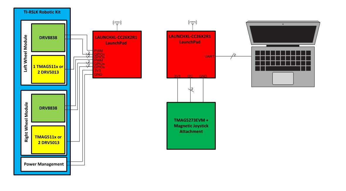
Two CC26x2R1 LaunchPad development kits can control the TI-RSLK robot wirelessly. One CC26x2R1 LaunchPad development kit is connected to the TI-RSLK kit while the other is connected to a PC. The PC LaunchPad development kit also has a TMAG5273EVM with a connected joystick attachment. When the joystick is pressed, the program moves the robot either forward or backward, where the speed of the robot is controlled based on how far the joystick is pressed in a direction. As the robot moves, the encoder outputs a number of pulses. The TI-RSLK LaunchPad development kits counts the number of pulses released and sends that information to the PC LaunchPad. The PC LaunchPad converts the number of pulses on each encoder output back into a frequency. The PC LaunchPad sends the encoder output frequencies across the LaunchPad’s application serial port at a baud rate of 115.2 kbps using 8 bits and one stop bit (8N1).
Figure 2-1 shows the block diagram of the system used to test the magnetic encoder.
 Figure 2-1 System Block Diagram.