SLYA060 August 2022 TMAG5110 , TMAG5110-Q1 , TMAG5111 , TMAG5111-Q1
6 How to Design With Hall-Effect Latches
Hall-effect devices may seem challenging to design for due to the complexity of magnetic equations and their non-linear behavior. Thankfully, with the help of design tools such as Ansys, Femm, or Magpy, we can simplify and streamline the design process by simulating the magnetic field (also referred to as B-field) behavior.
To select a Hall-effect sensor with adequate sensitivity for the magnet used in rotary encoding applications, we must consider a couple of items. The positioning and size of the magnet can have significant influence on magnetic flux density sensed by the Hall-effect sensor. Hall-effect devices are often available with multiple sensitivity options to suit the specific sensitivity requirements of an application. It is necessary to select a Hall-effect sensor with enough magnetic headroom to reliably trigger on changes in magnetic field.
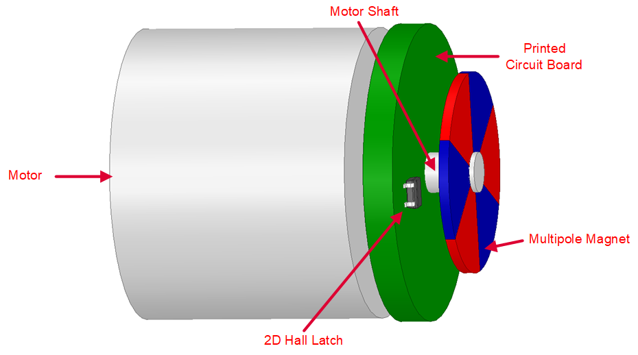
Magnetic incremental encoding is implemented by placing a magnetic disc on the motor shaft so that the disc rotates along with the motor shaft. The disc typically has multiple sets of north/south poles. A Hall-effect latch is placed underneath the magnet. As the ring magnet rotates over the sensor, the sensor detects the polarity changes in the magnetic field. The output of the device will change to either high or low as the magnetic field meets the BOP or BRP sensitivity specification of the Hall-effect latch. Figure 6-1 shows an example implementation for magnetic incremental encoding that uses one 2D Hall latch.
 Figure 6-1 Incremental Wheel Encoding With 2D Hall Latch.