SLYA065 October 2022 TMAG5328
4.1.1 Magnet Out-of-Range Testing (Magnetic Window Comparator Testing)
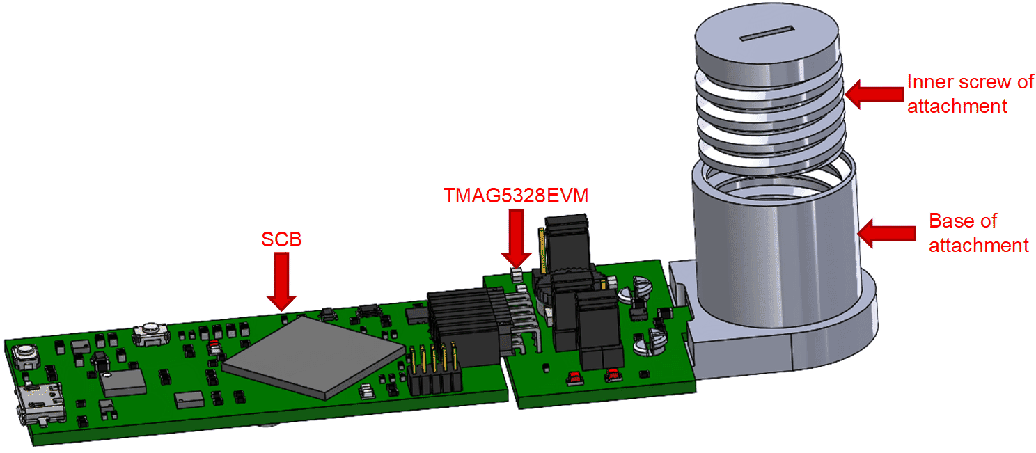
The out-of-range test provides an alert when the observed magnetic flux density is outside the system’s range of expected magnetic flux density readings. Out-of-range fault detection was specifically tested on the TMAG5328EVM by adjusting the position of the inner screw of the head-on linear displacement 3D print, as shown in Figure 4-3.
 Figure 4-3 TMAG5328EVM Connected to Head-On Linear Displacement 3D Print.
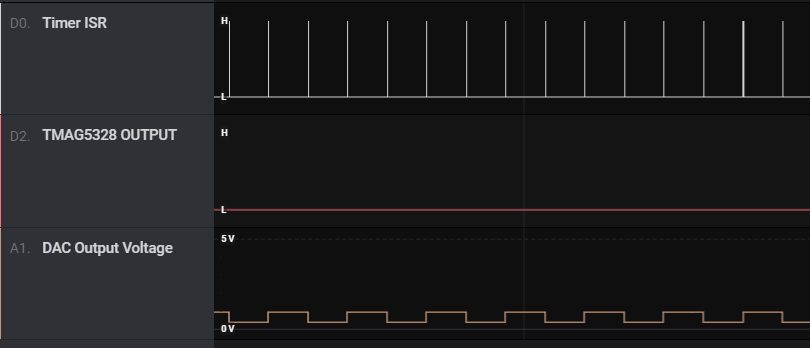
 In its initial state, the inner screw of the attachment, which has an embedded magnet, was placed so that the sensed magnetic flux density of the TMAG5328 was between 8.5 mT to 12 mT. The inner screw of the 3D print was screwed into the outer base until the sensed magnetic flux density was greater than 12 mT. Figure 4-3 shows the resulting logic analyzer screenshot, which shows that the TMAG5328 OUT pin is asserted low even when the DAC is in the high state. A square wave is no longer present on the TMAG5328 OUT pin, which means this diagnostic technique detected when the magnetic flux density was greater than 12 mT due to the magnet being too close. This scenario was also correctly logged by the EVM’s microcontroller as a fault condition.
 Figure 4-4 Logic Analyzer Screenshot of TMAG5328 OUT Pin When Magnet is Too Close (Sensed Magnetic Flux Density > BRP,HIGH).
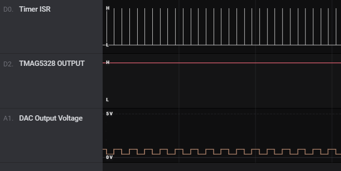
 Next, the inner screw of the 3D print was unscrewed until the sensed magnetic flux density was back to being between 8.5 mT to 12 mT, which resulted in a square wave appearing onto the TMAG5328 OUT pin again like it was in Figure 4-2. The inner screw was further unscrewed until the sensed magnetic flux density was less than 8.5 mT. Figure 4-5 shows the resulting logic analyzer screenshot from the sensed magnetic flux density being less than 8.5 mT. Figure 4-5 shows that the TMAG5328 OUT pin is asserted high even when the DAC is in the low state. A square wave is no longer present on the TMAG5328 OUT pin, which means this diagnostic technique detected when the magnetic flux density was less than 8.5 mT due to the magnet being too far or no longer present in the system. Additionally, the microcontroller was able to correctly to log this as a fault event.
 Figure 4-5 Logic Analyzer Screenshot of TMAG5328 OUT Pin When Magnet is Too Far (Sensed Magnetic Flux Density < BOP,LOW).
 This out-of-range test can also potentially detect if there is an external magnetic field present in the system that is causing the TMAG5328 device to see a magnetic flux density reading it should not normally observe.
After conducting the out-of-range test, the screw component of the 3D print was screwed back into the base so that the magnetic flux density was between 8.5 mT to 12 mT again so that the other faults can be detected.