SLYA075 august 2023 TMAG5110 , TMAG5110-Q1 , TMAG5111 , TMAG5111-Q1 , TMAG5231
Introduction
The main thrust of this article is electronic magnetic position sensor modules that pertain specifically to motion, but the document begins with separate discussions of sensors and modules. Sensors are devices that perform detection or monitoring and then respond to some sort of environmental input. This sensing device is typically in the form of an electronic integrated circuit (IC). An input from the real world can be heat, moisture, pressure, light, motion, or many other types of physical inputs. A module is an assembly – typically encapsulated in plastic or placed on a printed circuit board – containing several components, internally interconnected to perform a specific function. From these two definitions, it can be deduced that an electronic sensor module is an assembled unit with an onboard sensor and accompanying components to perform a certain function or task. However, remember that many providers of sensor modules also call these simply sensors.
Position sensor modules are in widespread use across industrial and automotive systems to monitor movement or position. These modules include volume control on audio equipment, stove top or dishwasher human-machine interface (HMI) control systems, automotive crankshaft systems, and so forth. Figure 1 through Figure 3 show examples of such sensor modules.
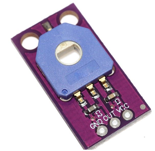 Figure 1 HW-526 Electronic Angle Sensor Module
 Figure 3 Single-Turn Rotary Position Sensor
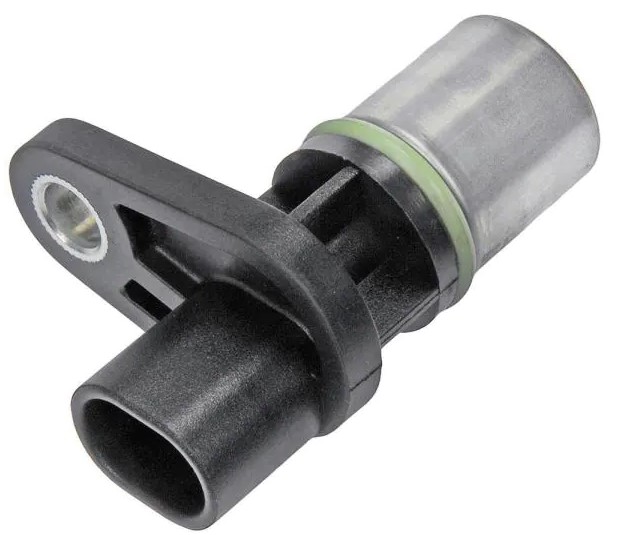 Figure 2 Automotive Magnetic Inductive Position Sensor
The sensor ICs available from Texas Instruments that are specifically developed for position sensing applications come in a variety of functions and technologies. Table 1 summarizes these TI sensor ICs.
| Function | Technologies Available | Typical Applications |
|---|---|---|
| Switch | Hall effect, Inductive |
|
| Latch | Hall effect |
|
| 2D Latch | Hall effect |
|
| 1D Linear | Hall effect, Inductive |
|
| 2D Linear | Hall effect |
|
| 3D Linear | Hall effect |
|
From this core set of functions, customers can develop many types of sensor modules that come in many shapes and forms. There are practically an endless number of modules available today. For demonstration purposes, TI tested two devices to see if TI devices meet or exceed the performance levels of these modules. The following sections contain the results of the tests.
Nidec® RMS20-256-201-1 Encoder
TI tested this encoder by mounting it onto a BLDC motor shaft using a 3D-printed structure to make sure the encoder was stable and level with the motor shaft. Figure 4 illustrates the setup.
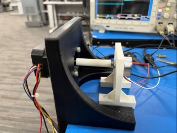 Figure 4 Motorized Encoder Test Setup
The Nidec encoder data sheet states a maximum 5-kHz frequency response. TI tested the encoder at various frequencies up to 5 kHz without any issues, and decided to crank up the frequency even higher to the maximum speed of the motor itself, which is 5,900 RPM. This produced a maximum output frequency of 25.25 kHz. Figure 5 shows the output of the signal waveforms at this high speed.
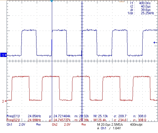 Figure 5 Nidec RMS20-256-201-1 Encoder Scope Capture
The encoder performed beyond TI's expectations and it performed flawlessly up to the rated frequency limit. Understandably, the encoder overheated very quickly at this high speed after even just a couple of seconds of operation. The temperature reached was not measured but the device was very hot to the touch. Due to the results, it seems obvious that the 5-kHz maximum limit imposed on the encoder was due to the mechanical internal assembly and not due to the electrical functionality of the sensor IC.
The two waveforms shown in Figure 5 are representative of incremental encoders. In perfect conditions, the waveforms are 90° out of phase from each other, allowing the user to monitor the speed and direction of a rotating shaft. Typically, two Hall-effect latches are used to do this. For more information, see the Incremental Rotary Encoders application note. Some ICs, such as the TMAG5110 and TMAG5111 have two latches built into a monolithic IC. With a 40-kHz signal bandwidth, these devices far exceed the requirements of the Nidec RMS20-256-201-1 encoder.
The Hall sensor bandwidth that is required to support a motor and magnet can be quantified with Equation 1.
Equation 1 shows that the motor, with a speed of 5,900 RPM, and a 10-pole magnet (or 5 magnet pole pairs) gives a sensor minimum bandwidth of 491.67 Hz, which is easily supported by the 40-kHz Hall-effect sensor. The potential of the 40-kHz Hall-effect devices is illustrated by considering two extreme examples. First, a 10-pole magnet requires a maximum motor speed of 480,000 RPM to exceed the supported 40-kHz Hall-effect bandwidth. A second example uses our 5,900 RPM motor, but requires > 400 magnet pole pairs to exceed the frequency range of the Hall-effect sensor. These two examples are impractical due to limitations in maximum motor speeds, manufacturability and reduction in magnetic fields produced by high-pole-count magnets, and so forth. The examples do illustrate the robust bandwidth margins Hall-effect devices can provide.
Honeywell® 103SR13A-1 Position Sensor
Figure 6 shows the test setup for another sensor module. The sensor, which is hermetically sealed in an aluminum threaded housing and responds to a South pole magnetic field, is positioned on the right side with a 3D-printed stabilizer. With the available equipment the magnet was positioned from the sensor with 0.5-mm increments.
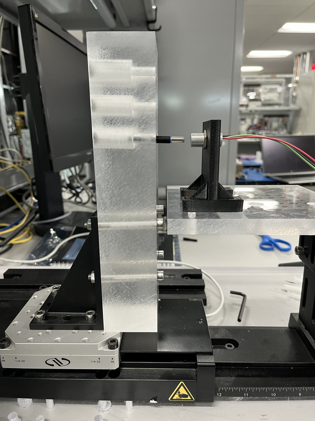 Figure 6 Motorized Positional Test Setup
The conditions for the testing of this sensor module follow:
- Room temperature (25°C) typical specifications for the BOP (magnetic operating point)
- BRP (magnetic release point), BHYS (magnetic hysteresis) are 35 mT, 27.5 mT, and 7.5 mT, respectively
Table 2 summarizes the distance measured in the lab at 25°C to activate and deactivate the switch with various cylindrical Neodymium magnet sizes and types (L denotes the magnet length and D is the diameter). The distances measured as shown in mm are from the edge of the sensor to the edge of the magnet. Because the sensor IC within the sensor module is slightly offset internally from the edge, the true sensing distance to the magnet is 1.27 mm longer and this value is added to the measured distance. The distance was also simulated using a magnetic position sensing tool that will soon to be available to customers. Table 2 also shows the magnetic operating and release points – derived from simulations – of a sensor IC required to activate and deactivate it. Notice these values are practically identical, as expected.
| Magnet | Activation Distance Measured (mm) | Simulated Activation Distance (mm) | Deactivation Distance Measured (mm) | Simulated Deactivation Distance (mm) | BOP Required (mT) | BRP Required (mT) |
|---|---|---|---|---|---|---|
| L-22 mm, D-3 mm | 4.27 | 4.35 | 5.77 | 4.94 | 35.28 | 27.53 |
| L-25 mm, D-3 mm | 4.77 | 4.37 | 5.77 | 4.96 | 35.35 | 27.54 |
| L-25 mm, D-5 mm | 5.77 | 5.24 | 6.77 | 6.12 | 34.97 | 27.49 |
| L-38 mm, D-5 mm | 6.77 | 7.26 | 8.27 | 8.24 | 34.96 | 27.35 |
| L-18 mm, D-6 mm | 8.77 | 8.31 | 10.27 | 9.38 | 34.98 | 27.19 |
| L-22 mm, D-6 mm | 8.77 | 8.44 | 9.77 | 9.53 | 34.93 | 27.25 |
| L-13 mm, D-13 mm | 14.77 | 15.48 | 16.77 | 17.31 | 34.61 | 27.44 |
| L-22 mm, D-13 mm | 15.77 | 16.70 | 18.27 | 18.90 | 34.97 | 26.96 |
| L-38 mm, D-13 mm | 17.27 | 17.97 | 19.77 | 20.27 | 34.57 | 27.00 |
Based on these results, the TMAG5231H1DQDMRR with a minimum BOP specification of ±30 mT and a BRP of ±23.5 mT can perform very well to closely match the performance distances of the Honeywell 103SR13A-1 position sensor. This device is available in the small X2SON package (1.1 mm × 1.4 mm) – very helpful in small, space-constrained modules such as this one.
These BOP and BRP values are actually representative of a sensor with a weak sensitivity specification. There are many devices that have much higher sensitivity levels such as the TMAG5231A1C version with a typical BRP threshold of 1.8 mT and a hysteresis of 0.6 mT. These higher-sensitivity designs allow the sensor module provider to develop tools that can detect magnets at a greater distance away or use smaller – and, subsequently cheaper – magnets.
Conclusion
There are position sensor modules for many types of applications in the industrial and automotive market available in the industry today and many more integrated circuit sensors that are used to develop these sensor modules. Two of these sensors were tested to show that the requirements of the modules are met easily with catalog designs from Texas Instruments providing sensor module manufacturers many devices to choose from.
To see the extent of TI's extensive portfolio, use the following links: