SLYA085 December 2023 TMAG6180-Q1
3.1 Input Related Errors
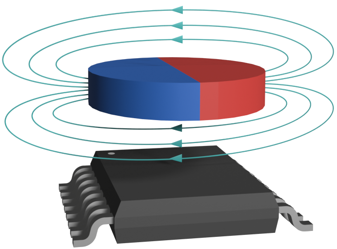
AMR angle sensors are two dimensional in design but the complete magnetic field vector is 3D. The field vector parallels the face of the magnet when a magnet is centered on the axis of rotation along the pole boundary.
 Figure 3-1 Correct Rotation
Alignment
Figure 3-1 Correct Rotation
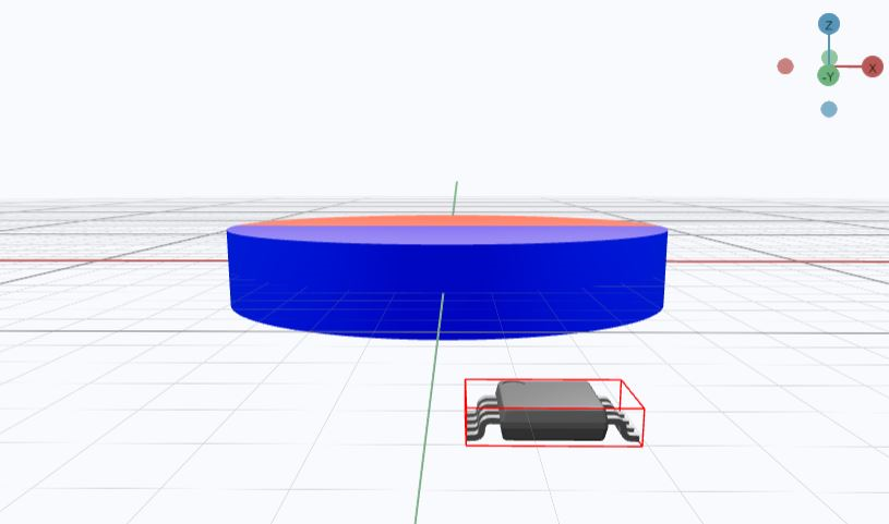
AlignmentAs a result, when the magnet rotates, the field vector is constrained in two dimensions and this produces the correct input for the sensor (Figure 3-1). The magnetic field vector varies in all three axes if the sensor is moved away from the axis of rotation.
 Figure 3-2 TMAG6180 With Mechanical
Offset
Figure 3-2 TMAG6180 With Mechanical
OffsetThe magnetic sensor is exposed to all three field components, with a circular profile presumption, but a significant portion of the input field in the z-direction is left undetected by the sensor. As a result, some input non-linearity is introduced. Consider the Lissajous plot in Figure 3-3 that uses the full vector and projection onto the XY plane when the Z component is ignored in Figure 3-4.
 Figure 3-3 3D Lissajous Plot
 Figure 3-4 2D Lissajous
Projection
Figure 3-4 2D Lissajous
ProjectionThe resulting input magnetic field angle changes at a different rate than the mechanical rotation measured because the resulting projection is elliptical instead of circular (the extremes for the X direction are ±45 mT while the Y direction is closer to 50 mT). The outputs generated by the device can take an unexpected form due to this non-linear change in angle. Careful examination of Figure 3-5 reveals that the output waveforms are slightly distorted and not demonstrating correct sine and cosine behavior.
 Figure 3-5 TMAG6180 Output Voltage with
Mechanical Offset
 Figure 3-6 Calculated Angle With
Mechanical Offset
 Figure 3-7 Angle Error Resulting From
Mechanical Offset
Figure 3-7 Angle Error Resulting From
Mechanical OffsetThe sensor outputs a non-linear angle calculation since the input to the sensor changes with a non-linear angle. This angle change is cyclical, so calibrating the sensor using techniques like multipoint linearization, a Look-up table, or harmonic approximation is available if necessary. These techniques are further described in Achieving Highest System Angle Sensing Accuracy.