SLYT796A august 2020 – August 2020 PCM1860 , PCM1861 , PCM1862 , PCM1863 , PCM1864 , PCM1865 , PCMD3140 , TLV320ADC3120 , TLV320ADC3140 , TLV320ADC5120 , TLV320ADC5140 , TLV320ADC6120 , TLV320ADC6140
4 Nonceramic Capacitors
For applications where the use of MLCCs must be avoided, other capacitor technologies exist. THD+N tests were also performed using the TLV320ADC6140 EVM[3] with these capacitor types:
- A standard 1-µF 0805 X5R capacitor.
- 1-µF surface-mount-technology (SMT) tantalum capacitor.
- 1-µF through-hole aluminum electrolytic capacitor.
- A 1-µF SMT film capacitor.
Figure 4 shows the data from this testing. As expected, the 1-µF SMT film capacitor offers the best performance over the full audio bandwidth, with the electrolytic capacitor as a runner-up. The film capacitor is available in a 1206 surface-mount package with a metallized acrylic dielectric and a 12-V rating.
When tested, other 1-µF film capacitors with polyester and polypropylene dielectrics and higher voltage ratings did not significantly deviate from the performance shown in Figure 4. The main drawback of film capacitors is their low relative permittivity. Thus, film capacitors tend to be much larger than their MLCC counterparts.
At the time of publication, the 1206 capacitor used in this testing was the smallest surface-mount 1-µF film capacitor readily available. Surface-mount values greater than 3.3 µF will require an 1810 package or larger, or traditional through-hole box-type packages.
On the other hand, tantalum and aluminum electrolytic capacitors tend to be smaller than film. Electrolytic capacitors have polarized dielectrics, meaning their anode must be kept at a higher voltage than the cathode or else the capacitor may be damaged. Taking two sets of measurements for these capacitors demonstrates the electrolytic effect. The first test applied a +5-V DC bias to the capacitors to ensure proper polarity. The second test applied no external bias, but the TLV320ADC6140 used for testing internally biases its inputs to 1.5 V, so these capacitors were actually slightly reverse-biased. Because of this internal bias, +6.5 V was provided at the input of the evaluation module for the +5-V test case. Comparing the two sets of data shows a significant difference in performance when polarized capacitors are not properly biased. High-performance applications must guarantee a positive DC bias or avoid the use of polarized capacitors for AC coupling.
This testing is not exhaustive; it is only designed to offer some high-level insights into the performance of different capacitor technologies. Many factors influence capacitor performance, and capacitors should be chosen carefully based on application needs. There is much debate in the audio community about the best metric to use for a capacitor. This article focuses on how differences in capacitors affect distortion in a real application.
 Figure 4 THD + N Variation with
Non-ceramic Capacitors
Figure 4 THD + N Variation with
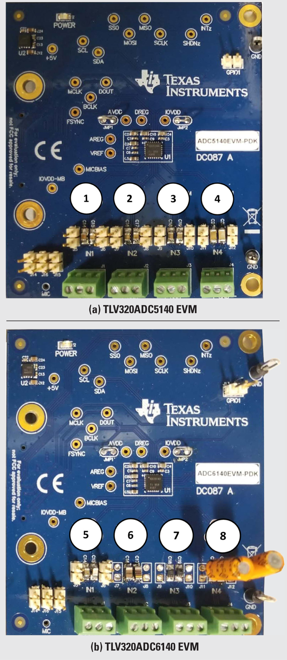
Non-ceramic CapacitorsFigure 5 shows the boards used for testing and Table 2 shows all of the capacitors included in this testing and their respective characteristics.
| Number | Type | Value | Voltage | Package |
|---|---|---|---|---|
| 1 | Ceramic X5R | 2.2 µF | 16 V | 0805 |
| 2 | Ceramic X5R | 4.7 µF | 16 V | 0805 |
| 3 | Ceramic X5R | 10 µF | 16 V | 0805 |
| 4 | Ceramic X5R | 47 µF | 6.3 V | 1206 |
| 5 | Ceramic X5R | 1 µF | 16 V | 0805 |
| 6 | Metal film | 1 µF | 12 V | 1206 |
| 7 | Tantalum | 1 µF | 35 V | 1206 |
| 8 | Aluminum electrolytic | 1 µF | 50 V | Radial through-hole |
| Not shown | Orange drop film | 1 µF | 100 V | Radial through-hole |
| Not shown | WIMA film | 1 µF | 50 V | Box |
| Not shown | Ceramic X7R | 4.7 µF | 16 V | 0805 |
 Figure 5 Evaluation Modules and Tested
Capacitors