SLYT796A august 2020 – August 2020 PCM1860 , PCM1861 , PCM1862 , PCM1863 , PCM1864 , PCM1865 , PCMD3140 , TLV320ADC3120 , TLV320ADC3140 , TLV320ADC5120 , TLV320ADC5140 , TLV320ADC6120 , TLV320ADC6140
3 Minimizing Distortion with MLCCs
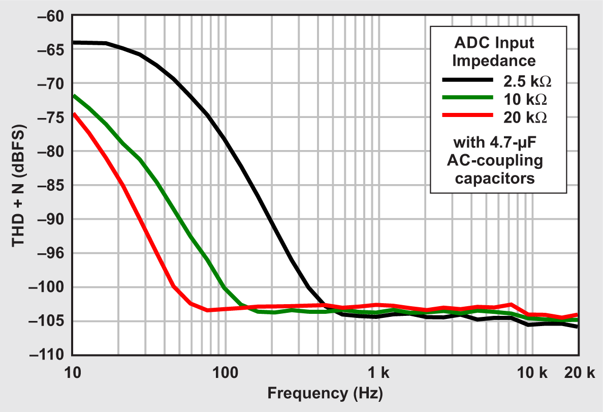
Minimizing the voltage drop across the capacitor will mitigate distortion. One approach to do this is to increase the impedance in series with the capacitor to limit the current flowing through it. To demonstrate this, total harmonic distortion-plus-noise (THD+N) measurements were taken on the Texas Instruments TLV320ADC5140 audio analog-to-digital converter (ADC) evaluation module (EVM),[2] with 4.7-µF X7R 0805 AC-coupling capacitors on the input. This ADC has a programmable input impedance that can be set to 2.5 kΩ, 10 kΩ or 20 kΩ. Figure 1 shows the results from a single channel with this capacitor while varying the input impedance with a 1-VRMS input signal.
Figure 1 shows that distortion increases at lower frequencies and peaks at the –3-dB cutoff frequency of the high-pass filter formed by the capacitor and the ADC input impedance. This is because the –3-dB point is where capacitor impedance equals the load impedance, which is when the voltage across the capacitor is highest. For cases with a 2.5-kΩ input impedance, the cutoff frequency is around 13 Hz, but the distortion starts much further out—around 400 Hz—and peaks around 13 Hz.
As expected, the change in distortion scales fairly linearly with increasing impedance. The drawback of this approach is that increasing the device’s input impedance degrades the signal-to-noise ratio performance by a few decibels. Moreover, adding series resistance externally also leads to additional noise and increases the gain error. The added gain error increases system complexity, since it may require calibration. For cost- or area-sensitive designs, increasing the impedance may work fairly well, but performance-focused designs will suffer with this approach.
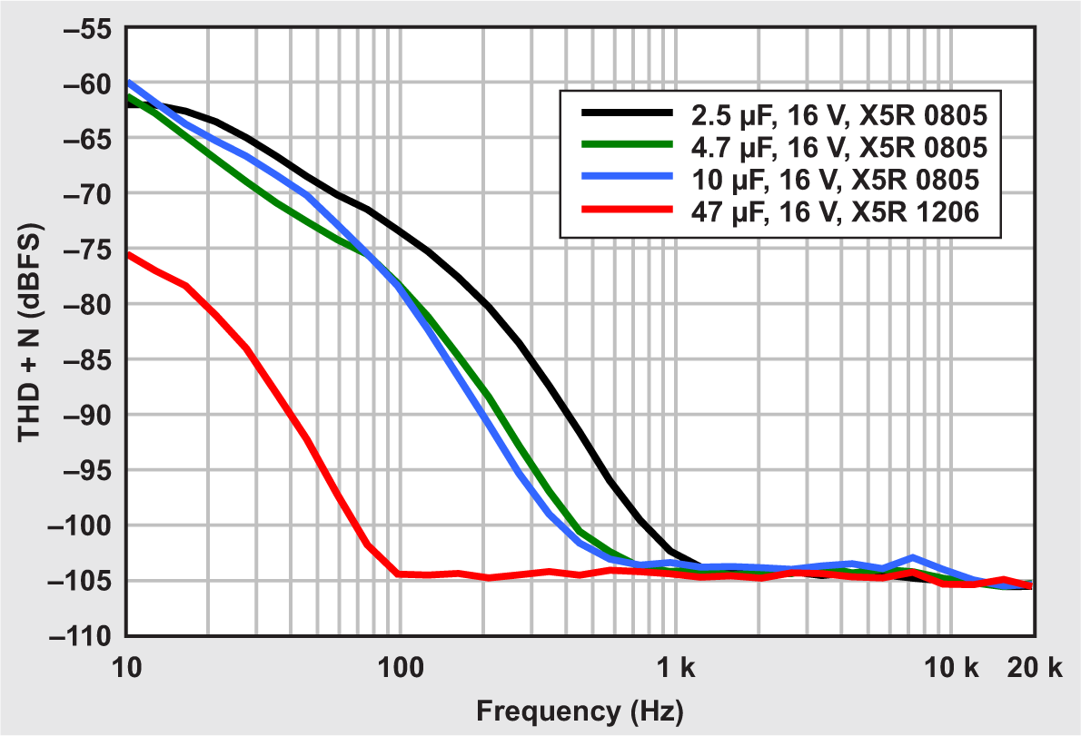
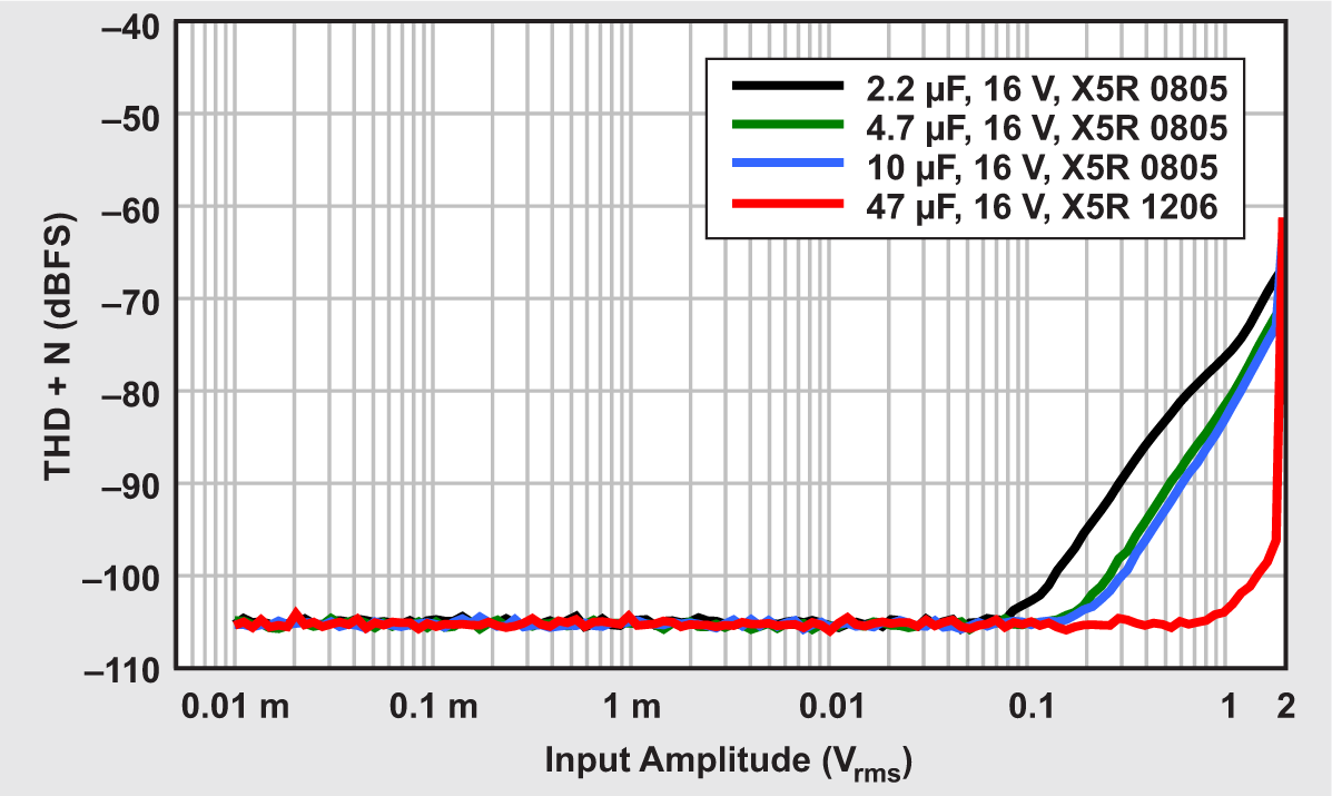
Another option is to increase the value of the capacitor until its impedance is low enough in the band of interest to reduce its distortion. Figure 2 shows the change in distortion over frequency, while Figure 3 shows the change in distortion over input amplitude as a result of varying the input capacitance for similarly rated capacitors. Note that the 47-µF capacitor tested was in a 1206 package, and increasing the package size will also tend to slightly reduce distortion. However, the dominant effect is still the dramatic increase in capacitance.
The data in Figure 3, taken with a 100-Hz input signal, shows that increasing the capacitance works fairly well for AC-coupling applications. MLCCs with capacitances greater than 47 µF are readily available in 0805 or 1206 packages.
 Figure 1 THD + N Variation with ADC Input Impedance
 Figure 2 THD + N Variation with AC Coupling Capacitance
 Figure 3 THD + N Variation with 100-Hz ADC Input Signal
Both of the approaches to mitigating distortion involve significantly reducing the cutoff frequency of the high-pass filter, either by increasing resistance or increasing capacitance. When using MLCCs for AC coupling, a good rule of thumb is to place the corner frequency two decades away from the specified passband. Or, worded differently, make the capacitor 100-times larger than needed or as large as can be reasonably supported. When using excessively large capacitors, even small amounts of series resistance will result in very low cutoff frequencies. This means that undesirable low-frequency noise, such as the typical 1/f noise of a complementary metal-oxide semiconductor front end, will not be filtered. Applying digital filtering further down the signal chain will suppress typical 1/f noise. However, it is still difficult to completely eliminate the influence of the ceramic capacitor in the bass region of the audio band. Applications demanding high performance will still benefit from the use of better technologies.
In many audio applications such as analog filter design, the preferred solution is to use C0G/NP0 ceramic capacitors because they have much better performance and are still available in small packages. While this is a great solution, it is not always feasible. In audio signal chains, keeping resistances low minimizes noise, but doing so requires increased capacitance for a given cutoff frequency. C0G/NP0 capacitors are not easily found in values greater than 1 µF, so they have limited utility in AC-coupling and other high-pass filter applications.