SLYT836 March 2023 IWR6443 , IWR6843 , IWR6843AOP
8 Calibration
To maintain performance across voltage and temperature variations, TI mmWave radar devices support boot-time calibrations at the RF initialization phase (calling the RfInit() application programming interface) as well as during runtime (during application execution). Figure 8-1 illustrates an example ordering of calibration types, which can include:
- Analog phase-locked loop calibration.
- Synthesizer VCO.
- Local oscillation distribution calibration.
- ADC DC offset.
- IF amplifier high- and low-pass cutoff frequencies.
- Peak detector.
- Transmit and receive gains.
- Quiescent current mismatch.
- Transmit phase shifters.
Figure 8-1 Timing sequence of functional chirping, monitoring and calibration.
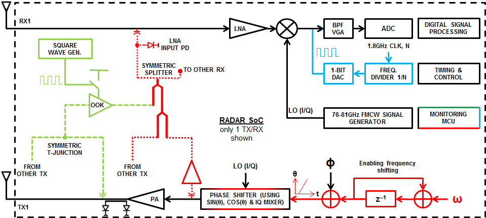
Figure 8-2 illustrates some of the integration in the RF front end for calibration of transmit, and receive analog front-end parameters. Along with power detectors for the PA outputs and LNA inputs, in combination with loopback paths, it is possible to continually monitor and compensate the complete front end.

Figure 8-2 Overview of the diagnostics and monitoring included in the IWR6843.