SLYT840 june 2023 INA333 , INA350
3 PCB layout
A PCB specifically designed for this comparison, containing the three circuits outlined above in a circular region, upon which the nozzle of a temperature forcing unit would fit. Care was taken to present the same input signal to each circuit, alleviating any concern for “leakage.” Each output was routed separately to ensure isolation.
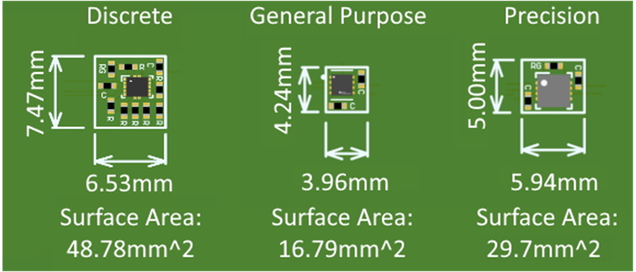
Figure 4 shows a simplified layout of each IA circuit to compare the relative sizes of each solution, including decoupling capacitors. For comparison purposes, the smallest device packages were used, along with resistors and capacitors in the 0402 package.
 Figure 4 Simplified PCB layout
comparison for dual-supply IA circuits.
Figure 4 Simplified PCB layout
comparison for dual-supply IA circuits.As you can see, the discrete IA implementation is significantly larger than the two integrated solutions. And with the integrated RG and overall smaller die size, the general-purpose IA layout is almost half the size of the precision IA layout.