SLYT859 September 2024 ADC32RF55 , DAC39RF12
2 What is frequency hopping?
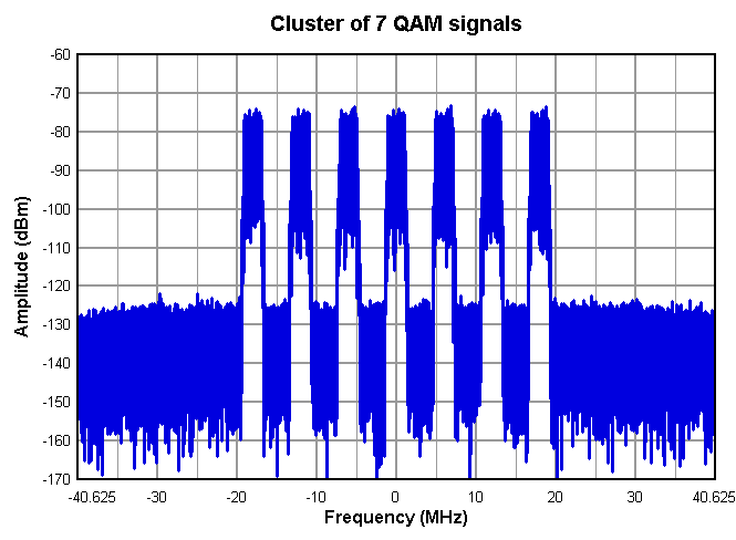
In modern communication systems, such as Wi-Fi® 6 and 7 or quadrature amplitude modulation (QAM)-encoded signals, the spectrum is inherently multiband, meaning that the radio-frequency (RF) domain consists of multiple channels within each frequency band. For instance, Wi-Fi 6 and 7 operate across several channels within the same frequency band to dynamically maximize bandwidth and data throughput, while QAM involves encoding data into different phase offsets and amplitude levels within a single channel. Figure 1 shows an example frequency band containing 7 QAM channels.
 Figure 1 Multitone signals in the
frequency domain.
Figure 1 Multitone signals in the
frequency domain.Direct RF-sampling analog-to-digital converters (ADCs) and digital-to-analog converters (DACs) incorporate many digital features. One of the most important features enabling direct RF sampling is the digital downconverter (DDC) in ADCs and the digital upconverter (DUC) in DACs.
In an ADC, the DDC consists of three main components: an NCO, digital mixer and decimator block. The NCO serves as the digital counterpart of the local oscillator in traditional receiver signal chains and mixes with the input signal to provide a signal in baseband (Nyquist zone 1), along with unwanted images. The decimator block filters out the images through a finite impulse response (FIR) decimation filter and then reduces the signal bandwidth by downsampling. The decimator block is the digital equivalent of an intermediate frequency (IF) filter.
In a DAC, the DUC comprises an interpolator, an NCO and a digital mixer. The interpolator, unlike in an ADC, upsamples the lower-bandwidth input signal and then passes it through a FIR filter to suppress images. After the interpolator stage, the output signal feeds into a digital mixer to mix with the NCO, allowing the DAC to operate over a wide Nyquist zone with a lower input signal bandwidth.
The number of DDCs active on any given input of an RF sampling converter determines whether a converter operates in single- or multiband output. This article’s focus will be on the ADC aspect of frequency hopping.
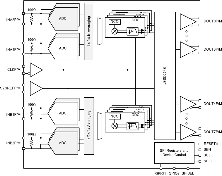
Figure 2 shows an example of the DDC from the Texas Instruments (TI) ADC32RF55, an RF-sampling ADC capable of dual-channel, quad-band operation at 3GSPS.
 Figure 2 Functional block diagram of
the ADC32RF55 (four DDCs per channel).
Figure 2 Functional block diagram of
the ADC32RF55 (four DDCs per channel).Often, the frequency band of interest may change: Instead of switching an entirely unique signal chain for each band, the same RF sampling converter can simply adjust the NCO frequency to match the new frequency band. This is a major advantage of modern RF-sampling converters. The act of changing the NCO from one frequency to a different frequency is what is known as frequency hopping.
The NCO does not produce an analog frequency directly; instead, it generates a digital representation of the desired frequency with high resolution. Each NCO receives a digital word – typically 48 bit or higher – which when combined with an NCO phase accumulator can represent a signal suitable for the digital mixing stage. When programming an NCO, the digital representation corresponding to the desired IF is what gets programmed, not an actual frequency. The NCO frequency range is most commonly supported between –Fs/2 and Fs/2, where Fs represents the converter’s sampling frequency. Negative frequency words are used for even Nyquist zones, while positive frequency words are used for signals in odd Nyquist zones.
To determine where a higher-order NCO frequency falls into baseband, your first task is to perform a modulus operation between the intended frequency and the sample rate to remove any multiple of Fs. The intended NCO frequency is now between 0Hz and the converter sample rate, Fs.
If the NCO frequency is less than the Nyquist frequency (Fs/2), then the intended NCO frequency translates to an odd Nyquist zone, as shown in Equation 1:
If the calculated NCO frequency is above the Nyquist frequency, then the frequency lands in an even Nyquist zone, as shown in Equation 2:
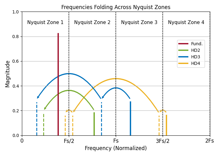
Figure 3 shows how a fundamental signal (Fund.) and its second-, third- and fourth-order harmonics (HD2, HD3 and HD4) will fold back into the first Nyquist zone, despite the actual frequency component landing in higher-order Nyquist zones.
 Figure 3 Harmonics folding across
high-order Nyquist zones into Nyquist zone 1.
Figure 3 Harmonics folding across
high-order Nyquist zones into Nyquist zone 1.One advantage of RF-sampling ADCs over traditional ADCs is that the hardware does not need to change in order to switch frequency bands. This inherent flexibility allows RF-sampling ADCs to quickly adapt to new frequency bands without requiring additional hardware components, simplifying system design and reducing costs. This process is not instantaneous, however. In early designs of RF-sampling ADCs, only a single NCO word option was available for each NCO and subsequent DDC. As a result, hopping to another frequency required multiple register-write operations.
The new NCO word must be written through the Serial Peripheral Interface (SPI), followed by another register write to push the new NCO word into the DDC block, where it actually takes effect. Several factors influence the time required to hop frequencies, including the length of the NCO word and the SPI transaction speed. Often, the register size of ADCs is limited to 8 bits, so you will need a total of seven register writes to update a 48-bit NCO: six register writes for the NCO word itself and one additional register write to update the DDC.
After considering the overhead for each SPI transaction (typically a 16-bit address for each register write), the transaction time triples. Assuming a 20MHz serial clock signal (SCLK) rate, Equation 3 calculates the time to frequency hop, assuming a nonstop stream of SPI data: