SLYT859 September 2024 ADC32RF55 , DAC39RF12
3 Evolution of frequency-hopping techniques
RF converters are now designed with multiple NCO words per DDC, allowing preprogramming of NCO words. This innovative approach enables faster frequency hopping by preloading several frequency values into the converter’s memory. This concept of storing precalculated NCO words is where the “fast” in fast frequency hopping comes from.
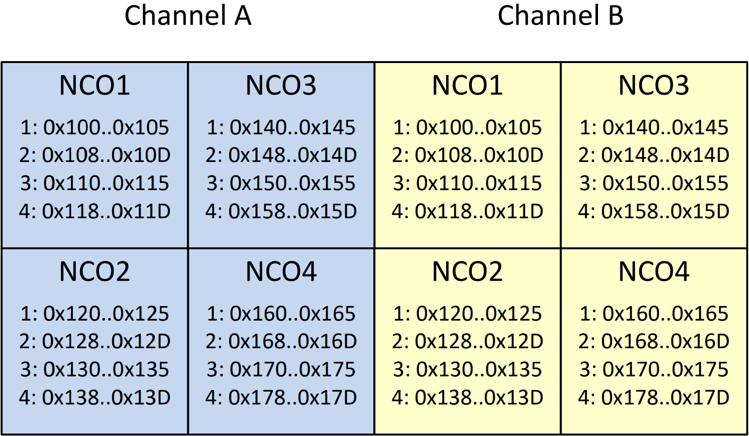
Figure 4 shows the 48-bit NCO register addresses by NCO index and word index for the ADC32RF55. Despite the addresses being the same for channel A and B, the frequency words are unique, as this device implements register map paging, which masks registers not included on the active page from any read and write operations.
 Figure 4 NCO word addresses by channel
and NCO index of the ADC32RF55.
Figure 4 NCO word addresses by channel
and NCO index of the ADC32RF55.Now that the words are programmed, how do you actually select a specific one? Changing the NCO word simply requires selecting a new NCO word for the DDC, which you can do through SPI or GPIO pins. Table 1 shows an example of how to select an individual word for the specified DDC in the ADC32RF55, depending on the number of active bands. In a standard configuration, this ADC has four unique NCO words per DDC; however, in single-band modes, the neighboring DDC’s four NCO words can supply the active NCO as well, meaning that each channel’s DDC has access to eight preprogrammed NCO words.
| # of bands | ADDR | D7 | D6 | D5 | D4 | D3 | D2 | D1 | D0 |
|---|---|---|---|---|---|---|---|---|---|
| Single | 0x3B | 0 | 0 | 0 | 0 | NCO2 CHA[1:0] | 0 | NCO1 CHA[1:0] | |
| 0x41 | 0 | 0 | 0 | 0 | NCO2 CHB[1:0] | 0 | NCO1 CHB[1:0] | ||
| Dual | 0x3B | 0 | 0 | 0 | 0 | NCO2 CHA[1:0] | NCO1 CHA[1:0] | ||
| 0x41 | 0 | 0 | 0 | 0 | NCO2 CHB[1:0] | NCO1 CHB[1:0] | |||
| Quad | 0x3B | NCO4 CHA[1:0] | NCO3 CHA[1:0] | NCO2 CHA[1:0] | NCO1 CHA[1:0] | ||||
| 0x41 | NCO4 CHB[1:0] | NCO3 CHB[1:0] | NCO2 CHB[1:0] | NCO1 CHB[1:0] | |||||
The time required to perform a frequency hop varies by converter. Typically, the SPI method requires the duration of just a single SPI transaction, instead of seven as in Equation 3. The speed of the SPI method is further limited by the maximum clock rate of the SPI and the overhead involved with serial data transmission. Assuming the same 20MHz SCLK, Equation 4 shows the time required before the device initiates an NCO word change:
In contrast, the GPIO method can be as fast as the GPIO inputs can be updated. Once the voltage crosses its high- or low-level thresholds, the NCO word change begins.
In either method, once the device receives the NCO word change, the internal NCO word updates instantly; however, the decimation filter has to flush out all old values, so there is some added delay as a result based on the decimation factor.
Table 2 shows the time required by the ADC32RF55 to flush its decimation filter with data from mixing with the new NCO frequency.
| Decimation setting | NCO switching time |
|---|---|
| /4 | ~250ns |
| /8 | ~350ns |
| /16 | ~600ns |
| /32 | ~1μs |
| /64 | ~2μs |
| /128 | ~4μs |
Generally, the GPIO approach will be faster than an SPI approach for frequency hopping because of the inherent parallel aspect of a GPIO interface vs. a serial interface. However, there is one consideration: In GPIO word-selection mode, the same word index will apply to all active DDCs. The device cannot use word 1 on DDC1 while using word 3 on DDC2; the GPIO interface will set all DDCs to the same word index.
Another method, FRI, involves sending data over specific device pins at a much faster rate than what standard SPI supports. Some devices, such as the TI DAC39RF12, can support FRI communication up to 200MHz, which you can use for selecting the active NCO word.