SLYU058D May 2021 – February 2024 TMAG5173-Q1 , TMAG5273
4.3 Joystick Demo
The TMAG5173EVM comes with the Joystick 3D print. However, this 3D print canalso work with the TMAG5273 since both devices use the same magnetic range. To use the joystick demo, follow these steps:
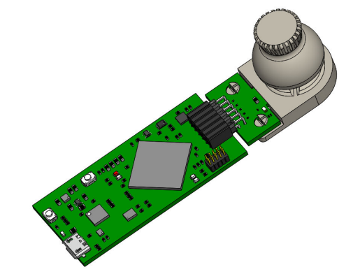
- Attach the joystick module to the EVM. See Figure 4-15 for an example on how this module is connected to one of the two TMAG5173 EVM
parts.
 Figure 4-15 Joystick Module on
EVM
 - In the GUI register page:
- Select the
DEVICE_CONFIG2 register and check the following:
- Make sure that drop-down menu option for the OPERATING_MODE register bits says 00b = Standby Mode (starts new conversion at trigger event)
- Make sure that drop-down menu option for the TRIGGER_MODE register bits says 0b=Conversion Start at I2C Command Bits
- Click the SENSOR_CONFIG1 register and select the 0011b= X, Y channel enabled option under the MAG_CH_EN drop-down menu to enable the X and Y channels. The user can also select the 0111b= X, Y, Z channel enabled option to enable the Z channel, but only the X and Y channels are required to observe the effect of the motion of the joystick. If the Z channel is enabled, then remember that this channel sees larger fields than the X and Y channel. Select the 1b = ±80 mT (TMAG5x73A1)/ ±266mT (TMAG5X73A2) option under the Z_RANGE register bit drop-down menu to make sure the Z_RANGE bit in the SENSOR_CONFIG2 register is set to 1.
- Select the
DEVICE_CONFIG2 register and check the following:
- Go to the Plots tab within the Results
Data page. Make sure that at least the X Component and Y Component
checkboxes are selected under the Results to collect/show box, then press
the COLLECT DATA button shown in Figure 4-16.
 Figure 4-16 GUI Before Data
Collection Begins With Joystick Module
Figure 4-16 GUI Before Data
Collection Begins With Joystick Module- When the user moves the
joystick around, the X and Y readings change.
 Figure 4-17 Example X and
Y Channel GUI Plots After Joystick Movement
Figure 4-17 Example X and
Y Channel GUI Plots After Joystick Movement- Note that different joysticks can have different magnetic readings for a specific joystick position due to differences in the installation position of the spherical magnet within the joystick. However, this can be dealt with by mapping the different joystick positions to the magnetic flux density readings during calibration, similar to the approach shown in this video: https://training.ti.com/designing-joysticks-hall-effect-sensors
- When the user moves the
joystick around, the X and Y readings change.
- Press the STOP COLLECT button to stop collecting data.
- After testing a particular TMAG5x73 device variant, make sure to first disconnect the SCB USB cable from the PC before connecting the SCB to another part of the EVM board associated with the other TMAG5x73 device variant. After disconnecting the cable, the part of the EVM board associated with the other TMAG5x73 variant must be connected to the SCB before reconnecting the SCB USB cable to the PC.