-
Dramatically Improve Your Lock Time with VCO Instant Calibration
Dramatically Improve Your Lock Time with VCO Instant Calibration
Trademarks
All other trademarks are the property of their respective owners.
1 Overview of Frequency Hopping
The ability to quickly switch between multiple frequencies, also known as frequency hopping, is a critical element in many systems, such as communications, defense radio, and electronic warfare. For these applications, it is imperative that switching between frequencies happens as quickly as possible.
For example, the Link-16 network used by NATO for transferring real-time tactical information requires frequency hopping under 13 μs.[1] [2]
Figure 1-1 illustrates the typical receiver architecture that requires one or more local oscillators (LOs) to generate the different frequency signals and mix them with an incoming receive signal.
 Figure 1-1 Typical Receiver
Architecture
Figure 1-1 Typical Receiver
ArchitectureIn such an architecture, the LMX2820 device can be used as an LO and simplifies the design with two key features: (1) integrating multiple VCO cores into one chip and (2) having ultra-fast VCO calibration. The eight VCO cores in the LMX2820 allow for wideband frequency coverage from 43.75 MHz to 22.4 GHz from a single IC, removing the need for multiple LOs. To switch quickly between these VCO cores, the Instant Calibration function of the LMX2820 device greatly reduces VCO calibration time to less than 5 µs, thus reducing the overall lock time.
This report gives an example of achieving a lock time of under 11 μs with the LMX2820. When compared with other calibration methods available today, it is clear that Instant Calibration provides the fastest solution for designing frequency hopping systems.
2 Integrated VCO Overview
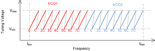
The Voltage Controlled Oscillator (VCO) converts a tuning voltage to an output frequency. It has become increasingly popular to integrate these on integrated circuits along with other functionality. To achieve good phase noise performance and wide tuning range, the VCO frequency range is typically divided into several overlapping bands. This allows the individual bands to have lower VCO gain, which corresponds to better VCO phase noise. By adding all the bands together, they can jointly create a wide tuning range. For this technique to work, a calibration routine has to be used to tell the VCO which is the proper band to use for a given frequency.
2.1 Integrated Silicon VCO Structure
Nowadays, PLLs with integrated VCOs on silicon technologies are very common for the reasons cost, size, wideband frequency coverage, and performance. To achieve good wideband performance while keeping good phase noise performance, it is common practice to use a series of switched capacitors and inductors.
 Figure 2-1 Simplified Tank Circuit for
Silicon VCO.
  Figure 2-2 Frequency Bands.
 Modern day synthesizers typically have more capacitors and inductors. For instance, the LMX2820 device has eight VCO cores and 192 different values in the capacitor bank to create 1536 total bands. Between these bands, there is overlap to allow for temperature drift and process variation. In addition to this, there is also an internal amplitude setting that varies as a function of frequency and temperature. So in summary, the three key parameters for the VCO Calibration to determine are:
VCO_ CORE: This is the inductor choice that greatly impacts the frequency band
VCO_CAPCODE: This is the capacitor bank setting that changes the frequency band
VCO_DACISET: This is the amplitude setting that optimizes phase noise
The purpose of the VCO calibration is to find the proper values for these three parameters. This calibration is activated by programmable serial commands when a change in frequency is desired.
2.2 Robustness and Consistency of VCO Calibration
The VCO calibration should be designed to be robust overtemperature. Even if the VCO is calibrated at one extreme temperature and it drifts to the other extreme temperature, the VCO should retain lock and not require reprogramming. For integrated silicon VCOs from Texas Instruments, one can choose to re-calibrate the VCO for some improvement, but this improvement in doing this is less than 1 dB in phase noise. As VCO is designed to tolerate wide temperature drifts, this implies that there is considerable overlap between the frequency bands. This leads to the next aspect of consistency of VCO calibration. As there is considerable overlap of the frequency bands, there are multiple frequency bands that can hit the same frequency. When the VCO does not choose the same calibration settings (VCO_CORE, VCO_CAPCTRL, VCO_DACISET), then there can be differences in spurs, VCO gain, VCO phase noise, and propagation delay. This is especially true if a different VCO core is chosen.