SNAA342 September 2020 LMX2820
4.3 Instant Calibration – The Ultimate to Blazing-Fast VCO Calibration
The LMX2820 introduces a new upgrade to full assist calibration called instant calibration. With this instant calibration, the same fast VCO calibration results can be obtained without so much programming and setup overhead. This has several advantages.
-
The calibration values for CAPCODE, CORE, and DACISET are always the same for the same frequency – giving consistent performance. This does assume power is not removed from the device, and there is an initial setup routine for the calibration that is required.
-
The VCO calibration time can be reduced to below 5 μs without compromising performance or reliability.
-
The LMX2820 features double buffering (shadow registers), which not only simplifies switching frequencies, but applies all the register settings for the new frequency at once, so that the VCO tuning voltage does not get slammed to the wrong value
Many different situations were measured using the initial setup condition as shown in Figure 4-2. The VCO frequency, dividers, and INSTCAL_FNUM values were changed, but the other conditions were the same. FCAL_INSTCAL_DLY was set to 250, which makes the VCO calibration time last for 2.5 μs.
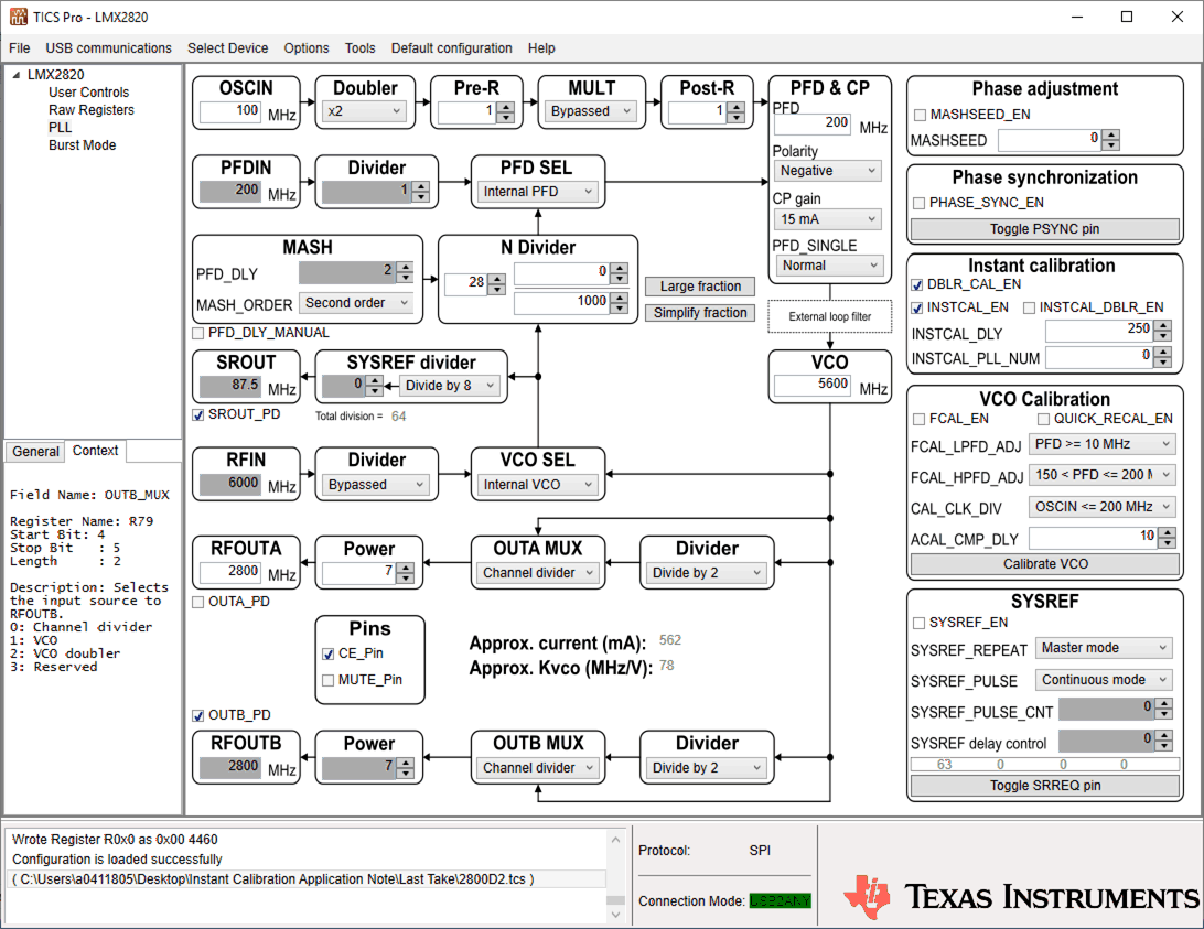 Figure 4-2 TICSPro Setup
The rest of the lock time is due to the analog settling time of the loop. The frequency error at the start of the analog calibration was measured (Δf) and the lock time was measured using the LD pin output and the results are recorded in Table 4-2.
| Output Frequency (MHz) | VCO Frequency (MHz) | Output Divider | dF (MHz) | Lock Time (μs) | |||
|---|---|---|---|---|---|---|---|
| Fstart | Fstop | Fstart | Fstop | DivStart | DivEnd | ||
| 5600 | 6000 | 5600 | 6000 | 1 | 1 | 6.7 | 11.8 |
| 6000 | 5063 | 6000 | 10126 | 1 | 2 | 0.5 | 9.8 |
| 5600 | 6053 | 5600 | 6053 | 1 | 1 | -3.2 | 9.7 |
| 6053 | 5600 | 6053 | 5600 | 1 | 1 | 1.4 | 10.9 |
| 5595 | 6028 | 11190 | 6028 | 2 | 1 | 14.5 | 12.2 |
| 6028 | 5595 | 6028 | 11190 | 1 | 2 | 2.2 | 9.5 |
| 2800 | 5600 | 11200 | 11200 | 4 | 2 | 0.9 | 11.9 |
| 5600 | 2800 | 11200 | 11200 | 2 | 4 | 2.2 | 10.8 |
The loop filter impacts the analog settling time of the loop and has some influence.
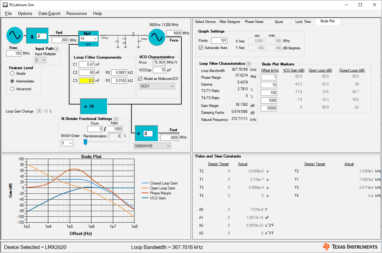 Figure 4-3 Loop Filter Setup
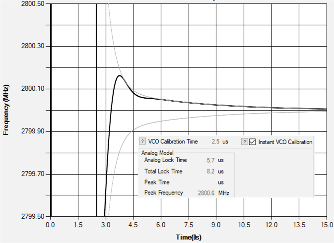 Figure 4-4 Lock Time Simulation
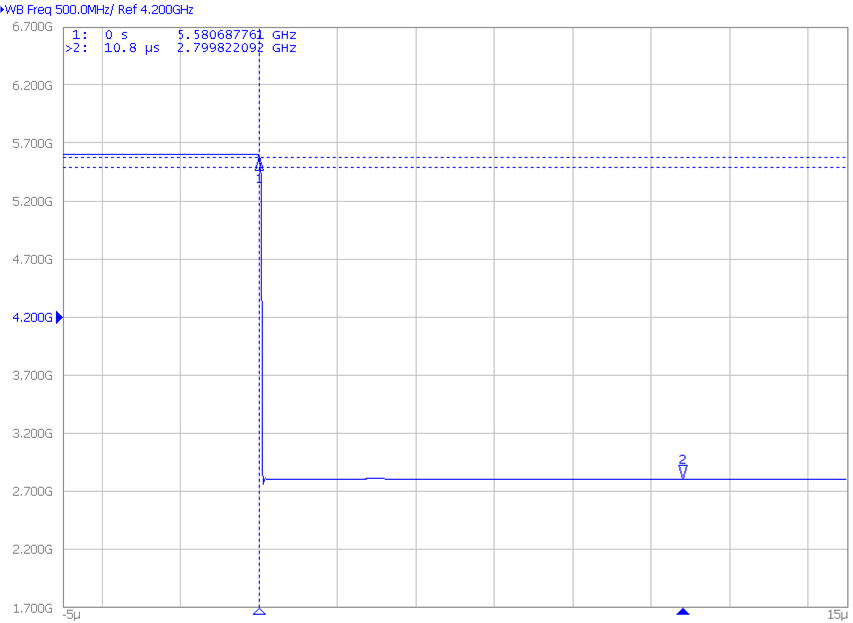 Figure 4-5 Wide Span Instant Calibration
With the LMX2820.
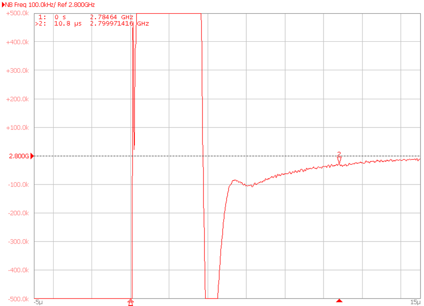 Figure 4-6 Narrow Span Instant
Calibration With the LMX2820.
 Figure 4-6 shows that at 10.8 μs, which is where the lock detect pin indicated lock, the frequency is slightly off on the order of 30 kHz. There is a long tail showing it gradually settling to this point, which sometimes can be improved by changing the capacitor type from X7R to C0G, although this was not attempted. In Figure 4-4 the frequency error after calibration was measured and the settling tolerance of 30 kHz was used and the simulation suggested 8.2 μs, compared to the actual measurement of 10.8 μs. In any case, regardless of measurement technique or capacitor types used, this lock time is blazing fast.