SNAA361A april 2022 – may 2023 LMX2820
5.1 External PFD Loop Filter Modification
When using the external PFD feature, the effective N-divider is 1 and the loop filter must be modified to maintain optimum results. The general strategy is to increase the loop bandwidth to take advantage of the low PLL noise as much as possible.
Use the PLLatinum simulation tool to provide a guide to optimize performance. To begin, start with the default values of the LMX2820 setup. As before, load the specific reference phase noise performance file. Keep the default VCO configuration as the internal VCO is still operational. Adjust the limits of integration to 10 kHz to 40 MHz as before. Change the charge pump current to 7 mA; this is the maximum value when operating in external PFD mode. Modify the loop filter to a 2nd-order passive topology; a simplified configuration is sufficient for the minimum divider case.
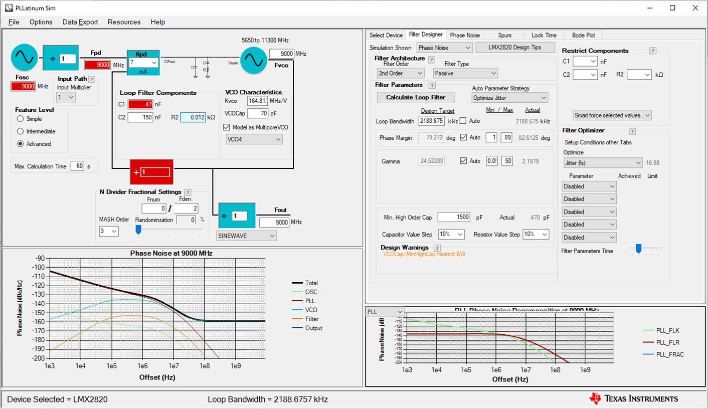
The tool does not specifically have a mode for external PFD operation. To simulate the external PFD configuration, set the Fosc and Fpd to the same value as the VCO output. This tricks the tool into setting the N-divider to 1. Disregard the red error highlights. With the default loop filter values and the N-divider set to one, the initial phase noise response shows a peaking response around 10 MHz.
Adjust the loop filter values to increase the bandwidth to compensate. Initially target a loop bandwidth around 2000 kHz. The automatic Calculate Loop Filter brings the values close to what is needed; afterwards, manually adjust loop filter values to hone in on an optimized and realizable filter. As before, there is no one absolute loop filter solution; Figure 5-2 shows the PLLatinum simulation set-up for the external PFD configuration used in this analysis and Table 5-1 shows the modified loop filter values.
 Figure 5-2 PLLatinum™ Simulation for External PFD
| Simulation Reference Designator | Value |
|---|---|
C1 | 470 pF |
C2 | 150 nF |
R2 | 12 Ω |