SNAA362 November 2022 LMK6C , LMK6D , LMK6H , LMK6P
4 Crystal Oscillators
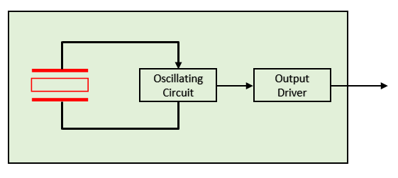
Quartz resonators are integrated in two different manners to make a standalone oscillator device; with each method presenting their own benefits and disadvantages. The first method, is to combine the crystal resonator with the oscillation circuitry and simply add the output driver to support different output types – this is usually called an SPXO, simple packaged oscillator.
 Figure 4-1 SPXO Crystal Oscillator Block Diagram
While this can be an elegant solution and present simplicity, small package, and quick start up time (as there is no calibration), it is very limited in frequencies it can support. The frequency support is purely dependent on the quartz crystal that is used. To support a different output frequency, a different crystal needs to have been assembled in the package as there is no capability to changed that post assembly. Furthermore, as the crystal resonator frequency is inversely proportional to the thickness of the crystal, that makes a crystal resonator operating at the fundamental frequency above ~50 MHz rare as they are extremely difficult to handle and manufacture. A more likely solution is to operate at an odd overtone of the fundamental, for example third-order overtone, meaning it’s operating at 3 times the fundamental frequency. When a crystal operates at the 3rd overtone, its resistance is about 3 times that of the fundamental, while it’s capacitance its almost nine times less – both changes which greatly impact the Q and the ability to tune the crystal.
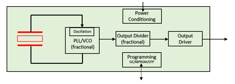
Another method for crystal integration, is to use the crystal as the reference to a PLL loop with a VCO operating at a much higher frequency (usually in GHz). From this GHz frequency then a simple divider and output driver can provide the specific output frequency needed at the specific output type. A fractional engine can be added, either in the PLL or the output divider, to increase the number of frequencies supported with single IC. These crystal oscillators will have some communication protocol (I2C or SPI) for simple register programming.
 Figure 4-2 Crystal Oscillator with PLL Block Diagram
While this is a more robust and flexible solution with one silicon having capability to support all frequencies, it has some drawbacks. Generally speaking because more core blocks are required (PLL, divider, etc.) this will lead to a larger package size (5 mm × 3.2mm, 7mm × 5mm) and higher current consumption (100+ mA). Lastly, the PLL calibration and lock will cause a slower start up time usually at or above 10 ms.
The cost of de-risking supply constraints, one silicon supporting all potential frequencies through different programming, is clear when it comes to size, power, and startup time.