SNAA365 June 2024 LMK5B33216
- 1
- Abstract
- Trademarks
- 1Hardware Architecture
- 2syn1588® Synchronization Algorithm
- 3Test Setup
- 4PTP System Application
- 5Additional Development
- 6Conclusion
- 7References
3.4 Compliance Test of Telecom Profile G.8275.2 - Partial Timing Support
For the test case purpose of networks with partial timing support, the PTP stacks on both leader and follower node devices are configured using default values of the PTP telecom profile G.8275.2.
The PTP event message rate details are listed:
- PTP domain number is 44.
- PTP event message rate is 64 packets per second.
- Announce message rate is 1 packet per second
- Announce timeout is 3 missing messages.
- Ethernet address type is unicast.
- Communication protocol is IPv4
The syn1588® PTP was configured as follows:
- The control loop parameters are set to slow mode, a setting optimized for high PDVs
- Sample rate converter filter is activated
- The non-linear spike prefilter is deactivated
- The non-linear lucky packet file is enabled with a packet buffer of 4069 packets and a median filter width of 3 packets.
- The clock is adjusted once every 8 seconds.
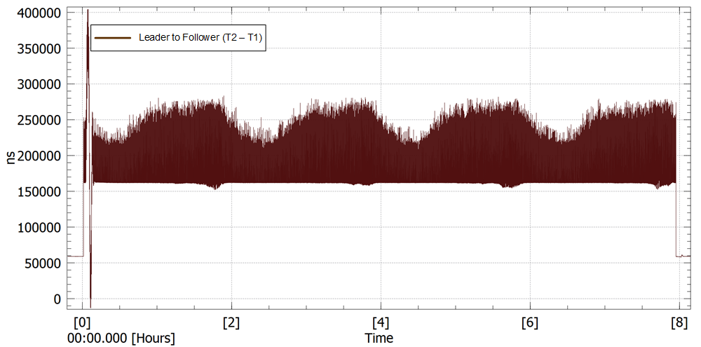
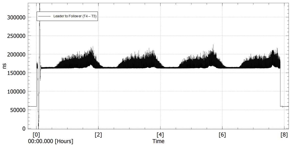
Initial test runs reveal that the syn1588® PTP Stack required further optimization to cope with the PDVs introduced by the Calnex system. A simple test is performed to analyze the noise level upstream and downstream of the signal. The ToD clock of the device under test is synchronized externally using the 1PPS signal provided by the Calnex. As soon as the device is sufficiently synchronized and test version of PTP Stack is invoked, the test processes all PTP messages and calculates the offset and path delay accordingly, while leaving the hardware clock unadjusted. Using the time stamp data in the log file, the impairment generated by the Calnex Paragon X can be analyzed.
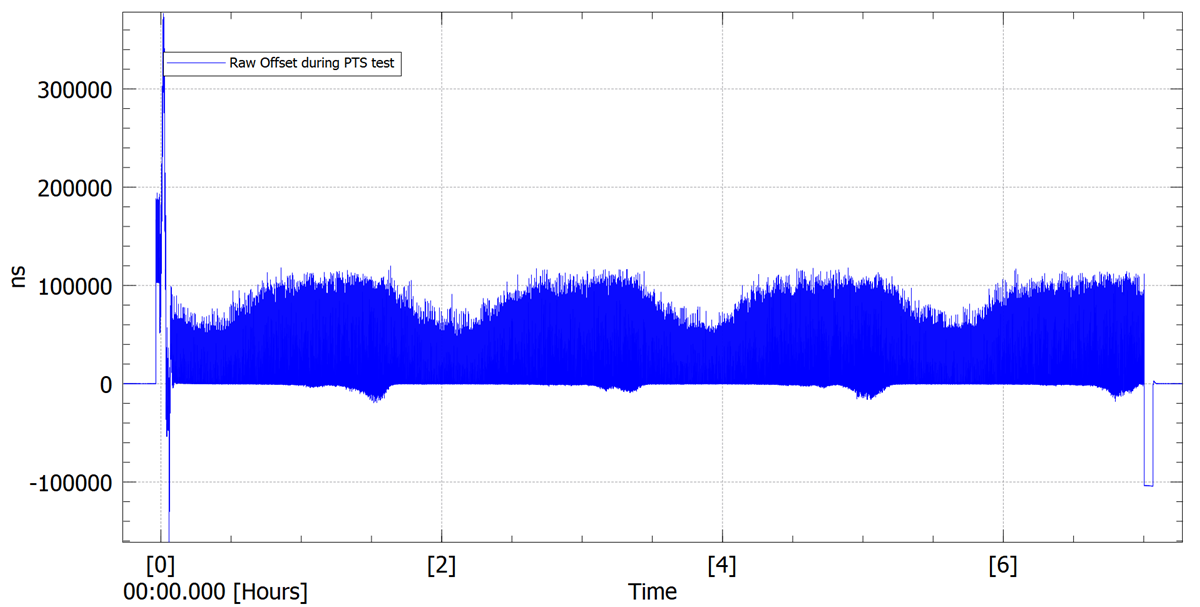
In Figure 3-10 the packet delay variations of the Sync messages (T2 – T1) are shown, while in Figure 3-11 the same data for the Delay Request Messages is provided (T4 – T3). The raw offset is calculated using the following formula:
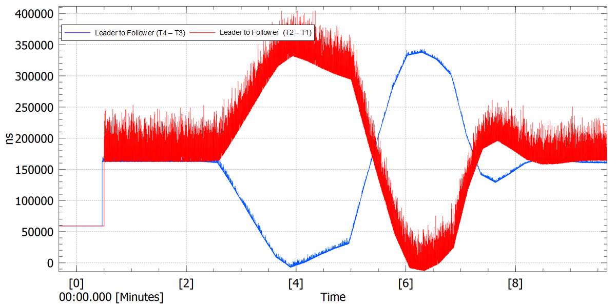
The resulting graph is shown in Figure 3-12. A detailed view of the initial phase of the impairment is provided in Figure 3-13.
 Figure 3-10 Leader to Follower Delay (T2-T1) During Impairment
 Figure 3-11 Follower to Leader Delay (T4-T3) During Impairment
 Figure 3-12 Offset Calculated Using (T1 … T4) During Impairment
 Figure 3-13 Upstream and Downstream Delay Variations
During Impairment (Capture is Zoomed in to Show the Beginning of the Test
Cycle)
Figure 3-13 Upstream and Downstream Delay Variations
During Impairment (Capture is Zoomed in to Show the Beginning of the Test
Cycle)To cope with changing conditions in the environment or setup, the PTP stack is configured to adjust the hardware clock once every 8 seconds. Additionally, the search window of the lucky packet filter is extended to 4069 packets. The test setup is as follows:
- Prior to enabling the test, the PTP stack is allowed to settle for 10 to 15 minutes. This long settling time is attributed to the servo parameter setting.
- The impairment is enabled and the 1PPS signal of the Leader and the Follower are monitored.
The results are shown in Figure 3-14. The test is repeated multiple times, yielding similar results.
 Figure 3-14 Absolute Time Error (Comparison of 1PPS Signals) for Partial Timing Support Test, Typical Measurement