SNAA379A July 2023 – September 2024 LMK6C , LMK6D , LMK6P
3 Universal Land Patterns for 6-pin DLE and DLF Packages
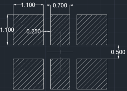
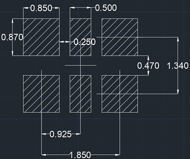
Six-pin DLE and DLF oscillators currently on the market tend to have varying placements of the corner pins, which leads to different footprints and land patterns that are often incompatible with each other. Installing an oscillator on an unsuitable land pattern results in overhangs that can potentially affect performance. TI’s universal land patterns in DLE and DLF sizes are one-size-fits-all designs that feature more generously-sized corner pads.
 Figure 3-1 Universal Land Pattern for 6-Pin, 3.2mm ×
2.5mm DLE Oscillators
 Figure 3-2 Universal Land Pattern for 6-Pin, 2.5mm ×
2.0mm DLF Oscillators
Figure 3-2 Universal Land Pattern for 6-Pin, 2.5mm ×
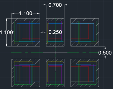
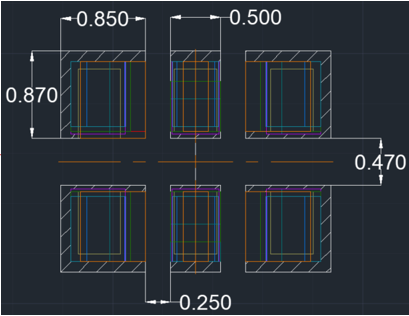
2.0mm DLF OscillatorsThe 6-pin DLE or DLF oscillators fit comfortably on the respective versions of the universal land pattern without overhangs. Figure 3-3 and Figure 3-4 show device footprints from both TI and many other vendors overlaid on the universal land patterns.
 Figure 3-3 6-Pin, 3.2mm × 2.5mm DLE Universal Land
Pattern Overlaid With 11 Device Footprints
 Figure 3-4 6-Pin, 2.5mm × 2.0mm DLF Universal Land Pattern Overlaid With 11
Device Footprints