SNAA406 August 2024 LMK6C
2.2 Star Line
The star line configuration is an alternative design designed for when loads are not co-located on a board. This configuration starts out as a single output line from the driver, then splits off closer to the receiver side. Star line routing is similar to the single-line approach, but with receivers that are further than 1" apart.
Line resistors (Rt) are added to aid in impedance matching so the driver sees a continuous 50Ω impedance. Rt is calculated according to the formula in Equation 1.
Where N is equal to the number of loads being driven and Z0 is equal to the characteristic impedance of the trace.
 Figure 2-4 Star Line Topology
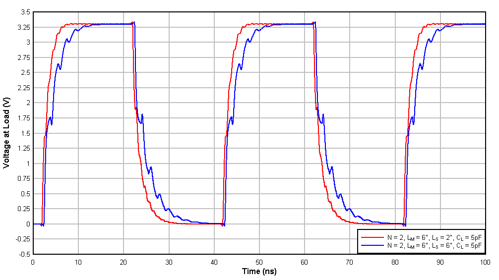
 Figure 2-5 Star Line Simulation
Results
Figure 2-5 Star Line Simulation
Results| Number of Loads | Trace Length - LS | Rise Time (ns) | Fall Time (ns) |
|---|---|---|---|
| 2 | 2" | 1.858 | 2.206 |
| 2 | 6" | 2.839 | 3.980 |
For star line configurations, as it is similar to the single line configuration, with only 2" of split trace length we see the rise and fall times are increased with very slight rippling. As the trace length increases to 6", rippling worsens and rise/fall time further increase. While this signal can be adequate to some receivers, increasing the split line length further can result in unacceptable signal integrity.