SNAA406 August 2024 LMK6C
2.1 Single-Line
This is the typical configuration for a single-ended signal. The single line configuration is recommended for the best signal integrity since the number of nodes are reduced to only one load per line. The single-line, single-load configuration is used as a benchmark for the other topologies that were tested.
 Figure 2-1 Single Line, Single Load
Topology
Figure 2-1 Single Line, Single Load
TopologyThe single-line, multi-load configuration is a good option for driving multiple loads when the separation between them is small. Some common use cases for this topology include driving two clock input pins on the same device, or multiple devices that are closely located. To be considered a single-line in the context of this study, the distance between loads need to be limited to under 1". The assumption is that each load is an equal distance from the main line, therefore LS is the same length for each receiver.
 Figure 2-2 Single Line, Multiple Loads
Topology
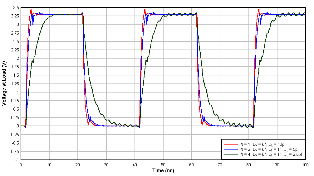
 Figure 2-3 Single Line Simulation
Results
Figure 2-3 Single Line Simulation
Results| Number of Loads | Trace Length - LM | Rise Time (ns) | Fall Time (ns) |
|---|---|---|---|
| 1 | 6" | 0.676 | 0.763 |
| 2 | 6" | 0.938 | 1.105 |
| 4 | 6" | 4.010 | 3.946 |
For single line configurations, driving two loads produces acceptable signal quality with only slightly longer rise and fall times and almost no measurable reflection artifacts.
With the addition of four loads, the rise/fall time slows significantly but there are still minimal reflections in the waveform.