SNAS854 February 2023 TDC1000-Q1
PRODUCTION DATA
- 1 Features
- 2 Applications
- 3 Description
- 4 Revision History
- 5 Pin Configuration and Functions
- 6 Specifications
- 7 Parameter Measurement Information
-
8 Detailed Description
- 8.1 Overview
- 8.2 Functional Block Diagram
- 8.3 Feature Description
- 8.4 Device Functional Modes
- 8.5 Programming
- 8.6 Register Maps
- 9 Application and Implementation
- 10Device and Documentation Support
- 11Mechanical, Packaging, and Orderable Information
8.3.2 Receiver Signal Path
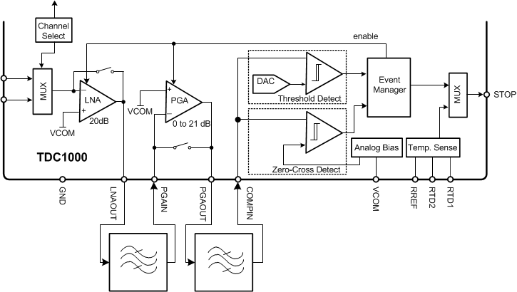
The RX signal path consists of a channel selection multiplexer followed by an LNA. The output of the LNA can then be sent to the PGA for additional amplification if needed. Finally, the signal is fed into a set of comparators which generate pulses on the STOP pin based on the programmed threshold levels. #SNAS6485090 shows the block diagram for the receiver path.
If the 20-dB to 41-dB of gain provided by the TDC1000-Q1 is insufficient, additional gain can be added prior to the COMPIN pin. Likewise, with a strong received signal, if the gain from the LNA or PGA is not be needed, they can be bypassed and the transducer signal could be directly connected to the COMPIN pin.
A band-pass filter centered on the transducer’s response can be used between each stage of the receiver path to reduce the noise; note that the inputs of the LNA, PGA and comparators should be biased to the VCOM pin’s potential. The comparators connected to the COMPIN pin are used for echo qualification and generation of STOP pulses that correspond to the zero-crossings of the echo signal. The STOP pulses are used with a START pulse to calculate the TOF of the echo in the medium.
 Figure 8-1 TDC1000-Q1 Receiver Path