SNAS854 February 2023 TDC1000-Q1
PRODUCTION DATA
- 1 Features
- 2 Applications
- 3 Description
- 4 Revision History
- 5 Pin Configuration and Functions
- 6 Specifications
- 7 Parameter Measurement Information
-
8 Detailed Description
- 8.1 Overview
- 8.2 Functional Block Diagram
- 8.3 Feature Description
- 8.4 Device Functional Modes
- 8.5 Programming
- 8.6 Register Maps
- 9 Application and Implementation
- 10Device and Documentation Support
- 11Mechanical, Packaging, and Orderable Information
8.3.3 Low Noise Amplifier (LNA)
The LNA in the TDC1000-Q1 front-end limits the input-referred noise and ensures timing accuracy for the generated STOP pulses. The LNA is an inverting amplifier designed for a closed-loop gain of 20 dB with the aid of an external input capacitor or resistor, and the LNA can be programmed for two feedback configurations. The band-pass configuration, referred to as capacitive feedback mode, must be combined with an input capacitor. The low-pass configuration, referred to as resistive feedback mode, must be combined with an input resistor. The recommended values for the input components are 300 pF and 900 Ω, respectively.
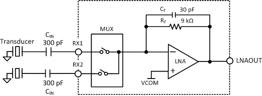
The LNA can be configured in capacitive feedback mode for transducers with resonant frequencies in the order of a couple of MHz. This is done by clearing the LNA_FB bit in the TOF_1 register to 0. As shown in #SNAS6482760, the external capacitor, CIN, should be placed between the transducer and the corresponding input pin. This provides an in-band gain of CIN/CF, where CF is the on-chip 30-pF feedback capacitor. Provided that CIN = 300 pF, the in-band gain of the LNA circuit is:

 Figure 8-2 LNA Capacitive Feedback
Configuration
Figure 8-2 LNA Capacitive Feedback
ConfigurationThe capacitive feedback configuration of the LNA has a band-pass frequency response. The high-pass corner frequency is set by the internal feedback components RF (9 kΩ) and CF (30 pF), and is approximately 590 kHz. The in-band gain is set by the capacitor ratio and the LNA’s 50-MHz gain-bandwidth product sets the low-pass corner of the frequency response. For example, an in-band gain of 10 results in a bandpass response between 590 kHz and 5 MHz.
The LNA can be configured in resistive feedback mode for transducers with resonant frequencies in the order of a couple of hundreds of kHz. This is done by setting the LNA_FB bit in the TOF_1 register to 1. In this configuration, the internal feedback capacitor CF is disconnected (see #SNAS6483714), and the DC gain of the LNA circuit is determined by the ratio between the internal feedback resistor RF (9 kΩ) and an external resistor RIN. For RIN = 900 Ω, the gain of the circuit is 10.
 Figure 8-3 LNA Resistive Feedback
Configuration
Figure 8-3 LNA Resistive Feedback
ConfigurationThe LNA can be bypassed and disabled by writing a 1 to the LNA_CTRL bit in the TOF_1 register.