SNAU198A May 2016 – May 2016 TDC7201
6 GUI and Operation
- If you haven’t done so, open the TDC720xEVM GUI. The EVM GUI software can be run by clicking on Start, then clicking All Programs, Texas Instruments, and TDC720xEVM and selecting TDC720xEVM.
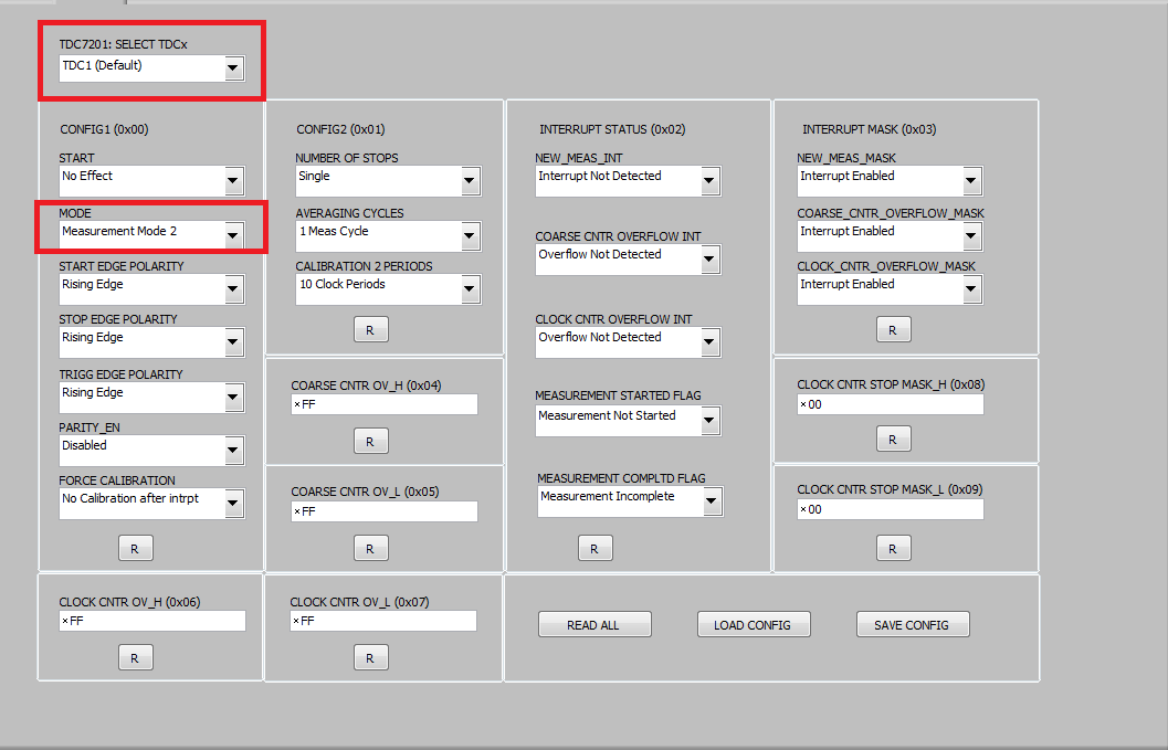
- Click on the TDC720x tab and make sure TDC1 is selected with the register configuration in Figure 8:
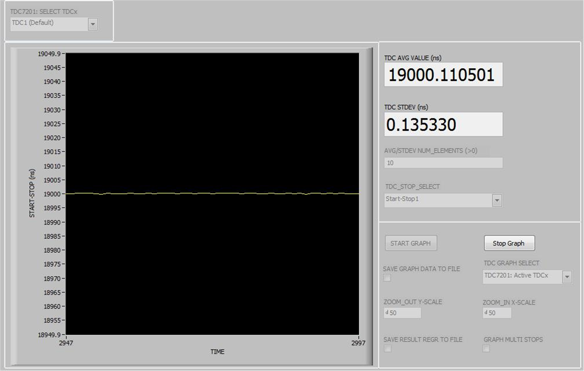
- Click on the Graph tab, then click on START GRAPH. You should be able to read 19 µs (assuming you follow the instructions as specified in Section 5.1).
- Calculating Time-of-Flight:
- In the GUI, click on the TOF_ONE_SHOT tab.
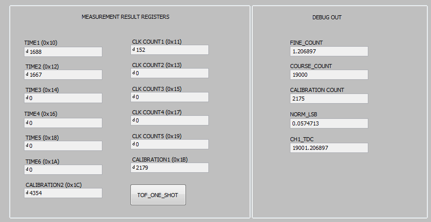
- You should be able to see similar measurement results register values as shown in Figure 10 (assuming you follow the instructions as specified in Section 5.1).
- To calculate the time-of-flight, use the Measurement Mode 2 Time-of-Flight calculation as shown in Equation 1. For more information, refer to the TDC7201 data sheet (SNAS686).
- Use the values reported in the Measurement Result Registers (Figure 10) to validate the time-of-flight as approximately 19 µs (assuming you follow the instructions as specified in Section 5.1).
 Figure 10. Measurement Results
 - TOFn [second] = time-of-flight measurement from the START to the nth STOP
- normLSB [sec] = normalized LSB value from calibration
- TIME1 = time 1 measurement given by the TDC7201 register address 0x10
- TIMEn+1 = (n+1) time measurement given by the TDC7201 register addresses 0x12, 0x14, 0x16, 0x18, and 0x1A
- CLOCK_COUNTn = nth clock count values in register addresses 0x11, 0x13, 0x15, 0x17, and 0x19
- CLOCKperiod [sec] = external CLOCK period
- offset [sec]= constant measurement offset
- CALIBRATION1 [count] = TDC count for first calibration cycle, located in register address 0x1B
- CALIBRATION2 [count] = TDC count for second calibration cycle, located in register address 0x1C
- CALIBRATION2_PERIODS = calibration count bits, located in register address 0x01
- START_EXT2/STOP_EXT2 Testing
- Modification to Input Signal Connections:
- Disconnect USB-to-SMA cable connection to START_EXT1 (J5). Instead, reconnect channel 1 of the dual function generator to TDC7201EVM’s START_EXT2 connector (J8).
- Disconnect USB-to-SMA cable connection to STOP_EXT1 (J4). Instead, reconnect channel 2 of the dual function generator to TDC7201EVM’s STOP_EXT2 connector (J7). See Figure 4.
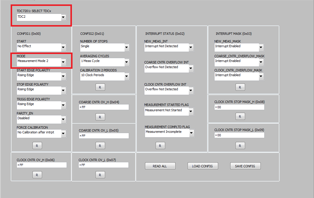
- Now repeat steps 1 through 4 from Section 6 with the following modification to step 2: Click on the TDC720x tab and make sure the TDC7201: Select TDCx field is as shown in Figure 11.
- Modification to Input Signal Connections:
 Figure 8. Recommended TDC7201:TDC1 Register Configuration
  Figure 9. Graphing
 Equation 1. 

where
Equation 2. 

 Figure 11. Recommended TDC7201:TDC2 Register Configuration