SNAU257 October 2020 TPL1401
3.2.2.4 Register Map Page
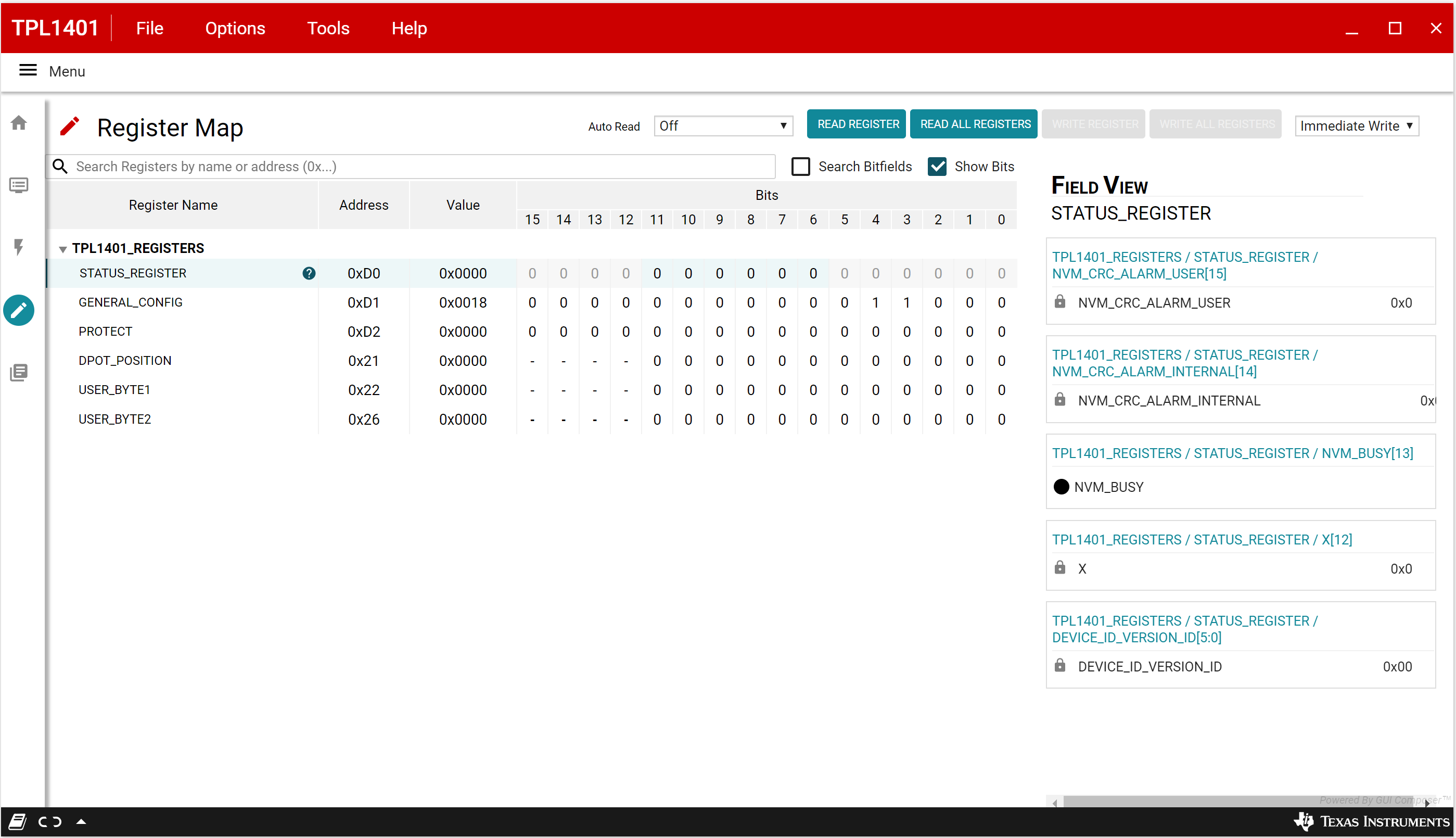
The TPL1401 EVM Register Map page, shown in Figure 3-8, allows the user to access low level communication directly with the TPL1401 registers. Selecting a register on the Register Map list shows a description of the values in that register, as well as information on the register address, default value, size, and current value. Values are read from and written to the registers by writing to the Value or bit field of the GUI.
 Figure 3-8 Register Map Page
There are some configuration lists and action buttons provided on the Register Map page. The values of the register map can be stored locally by pressing the Save Registers button under the File menu option. Additionally, the stored configuration files can be recalled and loaded through the Load Registers button. Other options selectable by the user are the Auto Read Interval,Read Register, Read All Registers, Write Register, Write All Registers, and Update Mode buttons. All buttons are displayed in Figure 3-9. The Write Register and Write All Registers buttons are enabled only with Deferred update mode. Deferred mode initiates a write operation only when the Write Register or the Write All Registers button is pressed. By default, the Immediate update mode is selected for the Register Map page write operations.
 Figure 3-9 Register Page Options