SNAU257 October   2020 TPL1401


  1.   Trademarks
  2. 1Overview
    1. 1.1 Kit Contents
    2. 1.2 Related Documentation from Texas Instruments
  3. 2System Setup
    1. 2.1 Software Setup
      1. 2.1.1 Operating Systems
      2. 2.1.2 Software Installation
      3. 2.1.3 Analog EVM Controller Firmware Upgrade
    2. 2.2 Hardware Setup
      1. 2.2.1 Power Configurations and Jumper Settings
      2. 2.2.2 Connecting the Hardware
      3. 2.2.3 Electrostatic Discharge Warning
  4. 3Detailed Description
    1. 3.1 Hardware Description
      1. 3.1.1 Theory of Operation for the BOOSTXL-DAC-PORT
      2. 3.1.2 Signal Definition of the BOOSTXL-DAC-PORT
      3. 3.1.3 Theory of Operation for the TPL1401EVM Hardware
      4. 3.1.4 Signal Definition of the TPL1401EVM
    2. 3.2 Software Description
      1. 3.2.1 Starting the Software
      2. 3.2.2 Software Features
        1. 3.2.2.1 Home Page
        2. 3.2.2.2 Setup Page
        3. 3.2.2.3 DIGIPOT Quick-Start Page
          1. 3.2.2.3.1 Basic DPOT Configuration Tab
        4. 3.2.2.4 Register Map Page
        5. 3.2.2.5 Collateral Page
  5. 4Schematic, PCB Layout, and Bill of Materials
    1. 4.1 BOOSTXL-DAC-PORT Schematic
    2. 4.2 TPL1401EVM Schematic
    3. 4.3 PCB Components Layout
    4. 4.4 BOOSTXL-DAC-PORT Bill of Materials
    5. 4.5 TPL1401EVM Bill of Materials

Connecting the Hardware

After the Analog EVM Controller firmware is upgraded as described in Section 2.1.3, and power and jumper configurations done as per Section 2.2.1, the BOOSTXL-DAC-PORT and TPL1401EVM can be connected as shown in Figure 2-6. Connect the USB cable from the Analog EVM Controller OTG USB Port (U7) to the PC.
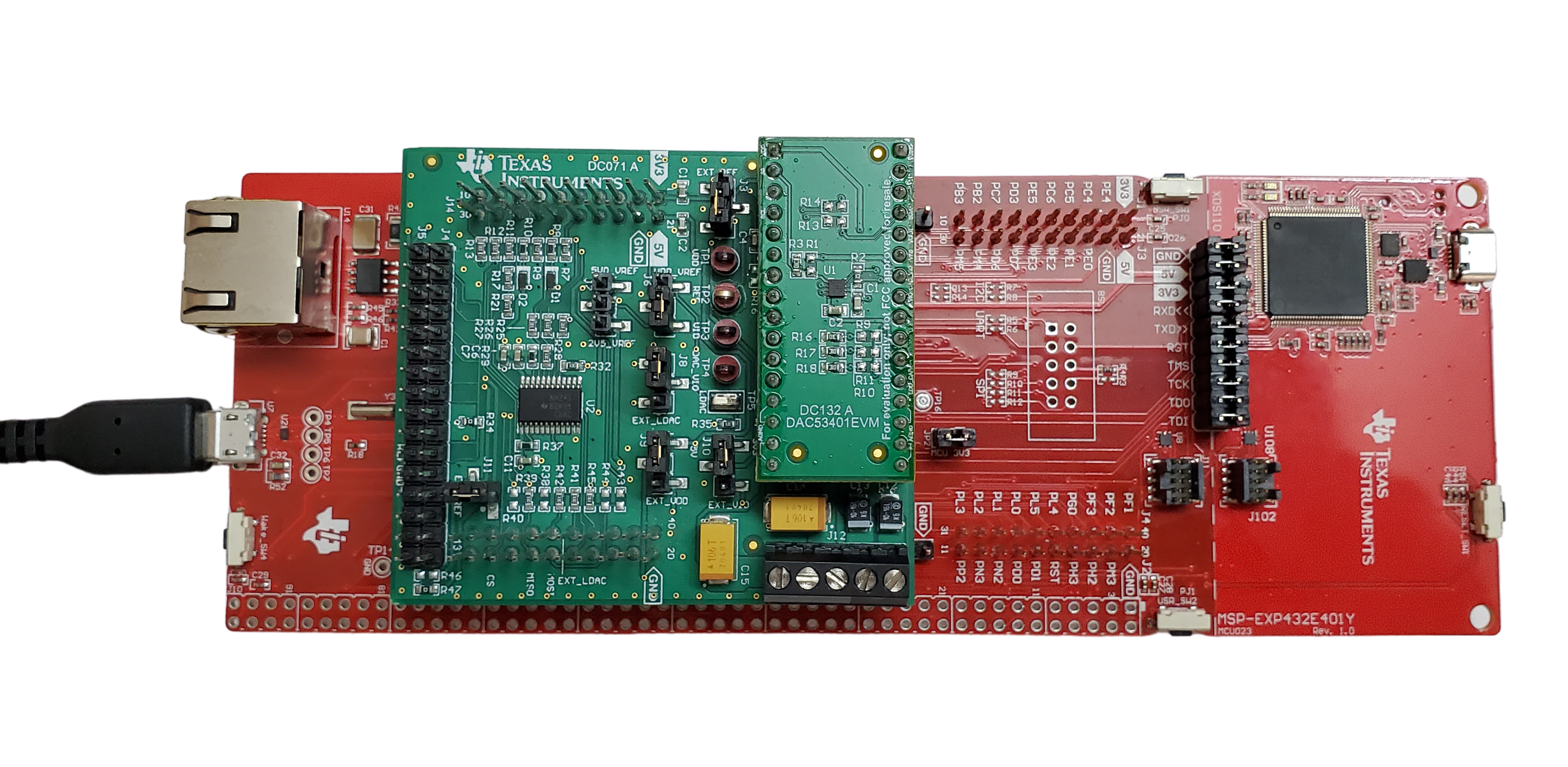
GUID-20200914-CA0I-HLDP-XXD7-V8J38TBMVKV4-low.pngFigure 2-6 Hardware Setup Guidelines