SNAU260A October 2020 – February 2021 LMK5C33216
ADVANCE INFORMATION
- Trademarks
- 1Introduction
- 2EVM Quick Start
- 3EVM Configuration
-
4EVM Schematics
- 4.1 Power Supply Schematic
- 4.2 Power Distribution Schematic
- 4.3 LMK5C33216 and Input Reference Inputs IN0 to IN1 Schematic
- 4.4 Clock Outputs OUT0 to OUT3 Schematic
- 4.5 Clock Outputs OUT4 to OUT9 Schematic
- 4.6 Clock Outputs OUT10 to OUT15 Schematic
- 4.7 XO Schematic
- 4.8 Logic I/O Interfaces Schematic
- 4.9 USB2ANY Schematic
- 5EVM Bill of Materials
- 6Appendix A - TICS Pro LMK5C33216 Software
- 7Revision History
2 EVM Quick Start
Table 2-1 describes the default jumper positions for the EVM to power the device from a single 4.5 V supply provided to VIN1. In positional information about jumpers, adj des means jumper is placed adjacent to designator. Opp des means jumper is placed opposite designator.
| CATEGORY | REF DES | POSITION | DESCRIPTION | |
|---|---|---|---|---|
| Power |
JP1 |
1-2 (adj des) |
DUT VDD = 3.3 V from LDO1 provided by U3. | |
|
JP2 |
1-2 (adj des) |
DUT VDDO = 3.3 V from LDO2 rail provided by U3. | ||
|
JP3 |
1-2 (adj des) |
LDO3 IN powered from VIN1 external supply. | ||
|
JP4 |
1-2 (adj des) |
XO VCC = 3.3 V from LDO3. | ||
| Communication |
JP5 |
1-2, 3-4 |
Connect I2C from onboard USB2ANY to DUT | |
| LMK5C33216 Control Pins |
S3 |
S5[1:2] = OFF |
SCS_ADD = no pull-up or pull-down. | |
|
S1, S2, S4 |
Sx[1,2] = OFF Sx[3,4] = ON |
Enable 3.9k pull-down on GPIO0, GPIO1, and GPIO2 | ||
To begin using the LMK5C33216, follow the steps below.
Hardware Setup
- Verify the EVM default jumper and DIP switch settings shown in Table 3-1.
- Connect Power, +4.5 V from an external DC power
supply (2-A limit), see Figure 3-2.
- To VIN1 & GND terminals on header J1 (pins 1 and 4), or
- To VIN1 SMA connector J2.
- Connect references.
- 156.25 MHz reference clock to IN0_P/N and/or,
- 10 MHz reference clock to IN1_P/N
- Connect USB cable to USB port at J41.
Software Setup
- If not already installed, install TICS Pro software from TI website: http://ti.com/tool/TICSPRO-SW
- If the MATLAB R2015b (9.0)* 64-bit runtime is not already installed, download and install from MathWorks website. While optional for programming and evaluating the default profile settings, the Matlab Runtime is necessary for any application that needs to modify the DPLL loop filter settings. See https://www.mathworks.com/products/compiler/matlab-runtime.html
- Start TICS Pro software
- Select the LMK5C33216 profile from Select Device → Network Synchronizer Clock (Digital PLLs) → LMK5C33216
- Confirm communications with board by
- From the menu bar, click USB communications.
- Click Interface
- In Communication Setup pop-up
window.
- Ensure USB2ANY is selected as the interface.
- In case of multiple USB2ANY, select desired interface. If a USB2ANY is currently in use in another TICS Pro, you must release that interface by changing its interface setting to DemoMode
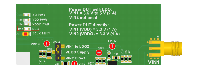
- Click identify to blink LED illustrated in Figure 2-1. This confirms you are connected to the board you expect.
 Figure 2-1 USB LED
Program LMK5C33216
- Toggle switch S5 (PDN/RESET).
- Program all the registers by…
- Pressing Write All Regs button in toolbar
- From the menu bar click USB Communications then click Write All Registers, or
- Pressing Ctrl + L.
- Current consumption should be approximately 1.15 A.
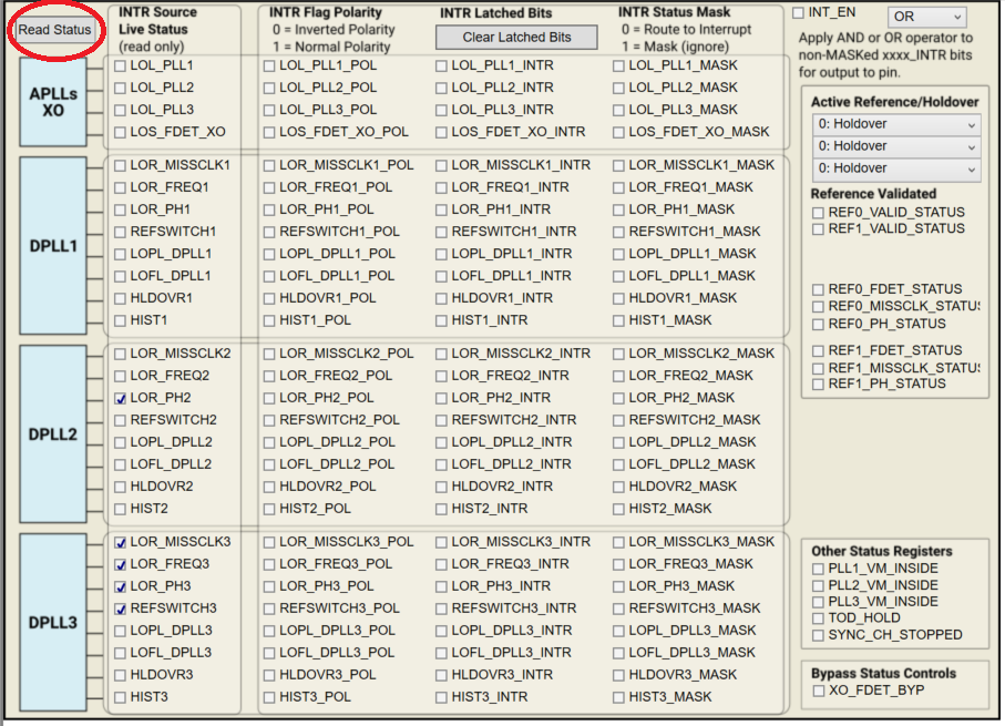
- Check LMK5C33216 Status
- Status Page of GUI
- Click Read Status Bits
- To clear latched bits.
- Press Clear Latched Bits button
- Read Status Bits
- It may take some time for the DPLL status bits to reflect lock.
 Figure 2-2 Read Status Bits
Measure
Measurements may now be made at the clock outputs.