SNAU270 February 2022 LMK1D1208I
5 Power Supply Connection
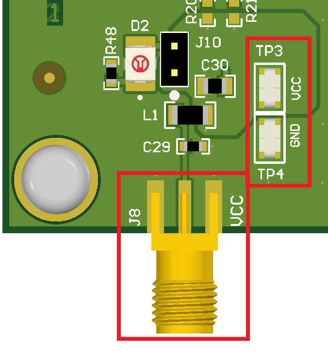
Connect the power supply source to the SMA connector, J8 (VDD). Test points, TP3 (VCC) and TP4 (GND), can be used as an alternative power supply source. The decoupling capacitors and ferrite bead isolate the EVM power from the power pins of the device.
A supply voltage of 1.71 V to 3.465 V can be used for this EVM.
 Figure 5-1 Power Supply Connection
Layout.