SNAU273 December 2022 LMX2820
3.2 Category 2 SYNC Example
According to the SYNC category flow chart, there are two possible paths that a configuration can fall into Category 2 SYNC.
The above configuration is a Category 2 SYNC, because:
- M = 1
- fOUT is an integer multiple of fOSCIN (3000 / 100 = 30)
- Channel divider is not bypassed
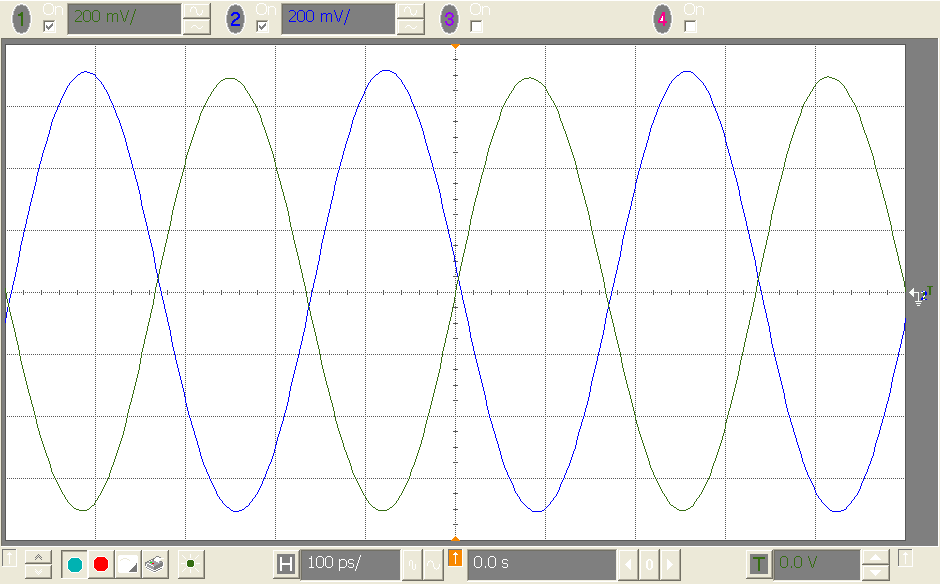
With the channel divider set to divide by 2, there are two possible output phases: 0° or 180° (read the application note in Section 5 for details). In other words, every time we setup the test, we have a 50% chance that both LMX2820 devices are phase-aligned.
 Figure 3-8 Before Phase Synchronization
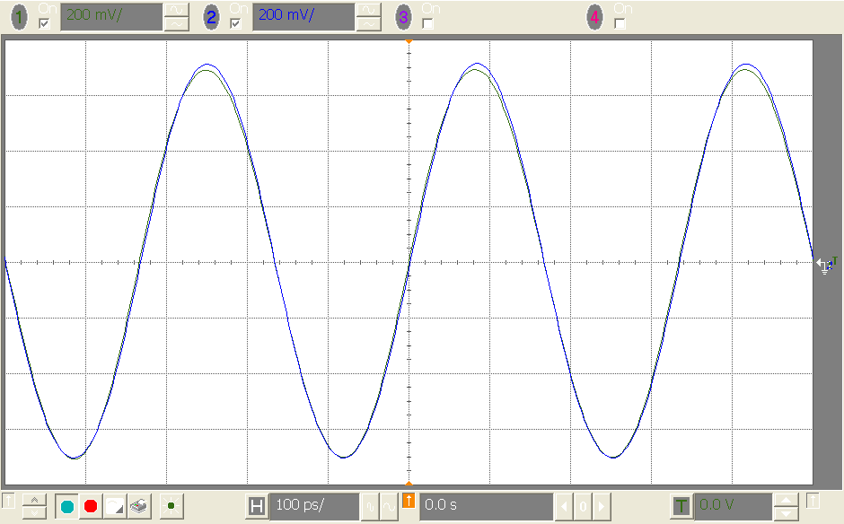
To get both LMX2820 devices phase synchronized, first we must put both devices in SYNC mode and set PHASE_SYNC_EN = 1. We require a SYNC pulse to trigger phase synchronization, therefore set INPIN_IGNORE = 0 to activate the PSYNC input pin (pin 5). The timing of the SYNC pulse is not important. As long as there is a Low-to-High transition at PSYNC pin, the synchronization process is executed. If we are using TICS Pro and USB2ANY to control the LMX2820 EVM, we can press the Toggle PSYNC pin button once and the USB2ANY will set the PSYNC pin from Low to High and then High to Low.
 Figure 3-9 After Phase Synchronization
Below is another Category 2 SYNC example. This time, the output frequency is smaller than the reference clock frequency:
- M = 1
- fOUT is not an integer multiple of fOSCIN
- fOSCIN is an integer multiple of fOUT (100 / 50 = 2)
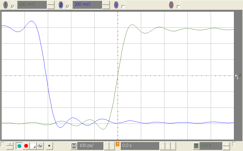
The output is heavily divided down to 50 MHz, therefore there are many possible phase relationships between the two LMX2820 devices.
 Figure 3-11 Possible Phases Before Synchronization
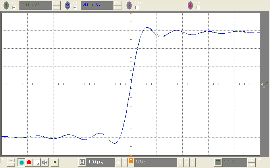
Again, a non-timing critical SYNC pulse is required to get the outputs synchronized.
 Figure 3-12 Phases Matched
In Category 2 SYNC, the LMX2820 devices must be synchronized again if:
- LMX2820 is powered down and powered up again
- VCO is calibrated again
- LMX2820 is reset and re-programmed