SNAU274 December 2021
2 Hardware and Software Installation
The ADC128S102EVM is out of the box ready to use, and requires minimum set up.
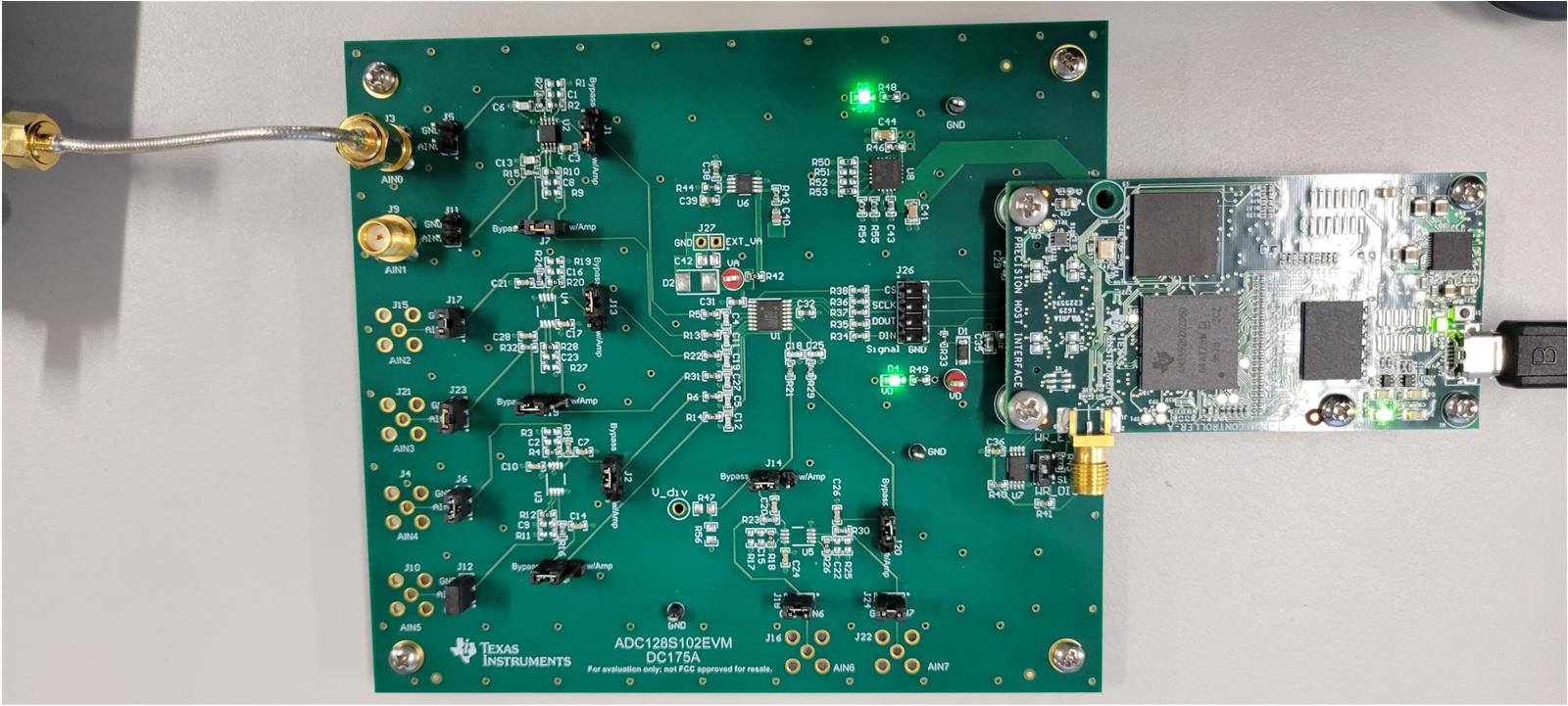
- Remove any screws from J25 on the EVM. Connect the PHI board on J25, and remove any stand offs on the PHI. Reinstall the screws to secure the PHI to J25, being sure not to overtighten. Figure 2-1 shows an example of the hardware set up.
- Connect the micro USB cable to the PHI, and the other end to the computer to be
used.
 Figure 2-1 ADC128S102EVM
Connected to PHI
 - On the ADC128S102EVM Product folder, download the user-friendly GUI. This action prompts a file download. Open the folder when available and run the executable file.
- You may be prompted to download and install LabView™, in particular for first-time users. Complete the necessary installations by accepting any pop-up windows.
- When the install is complete, the option to run the GUI or create a desktop short cut is offered. If a shortcut is not created, the GUI can be accessed at C:\Program Files (x86)\Texas Instruments\ADC128S102 EVM.
- On the bottom panel, as shown in Figure 2-2, the GUI displays a green ball next to HW Connected when the GUI successfully connects to the hardware. Also, the hardware has two green LEDs illuminated after a successful connection is made.
 Figure 2-2 GUI Successfully
Connected