SNAU283 October 2022
- Abstract
- Trademarks
- 1Evaluation Board Kit Contents
- 2Quick Start
- 3PLL Loop Filters and Loop Parameters
- 4Default TICS Pro Mode
- 5Using TICS Pro to Program the LMK04368-EP
- 6Evaluation Board Inputs and Outputs
- 7Recommended Test Equipment
- 8Schematics
- 9Bill of Materials
- A USB2ANY Firmware Upgrade
- B TICS Pro Usage
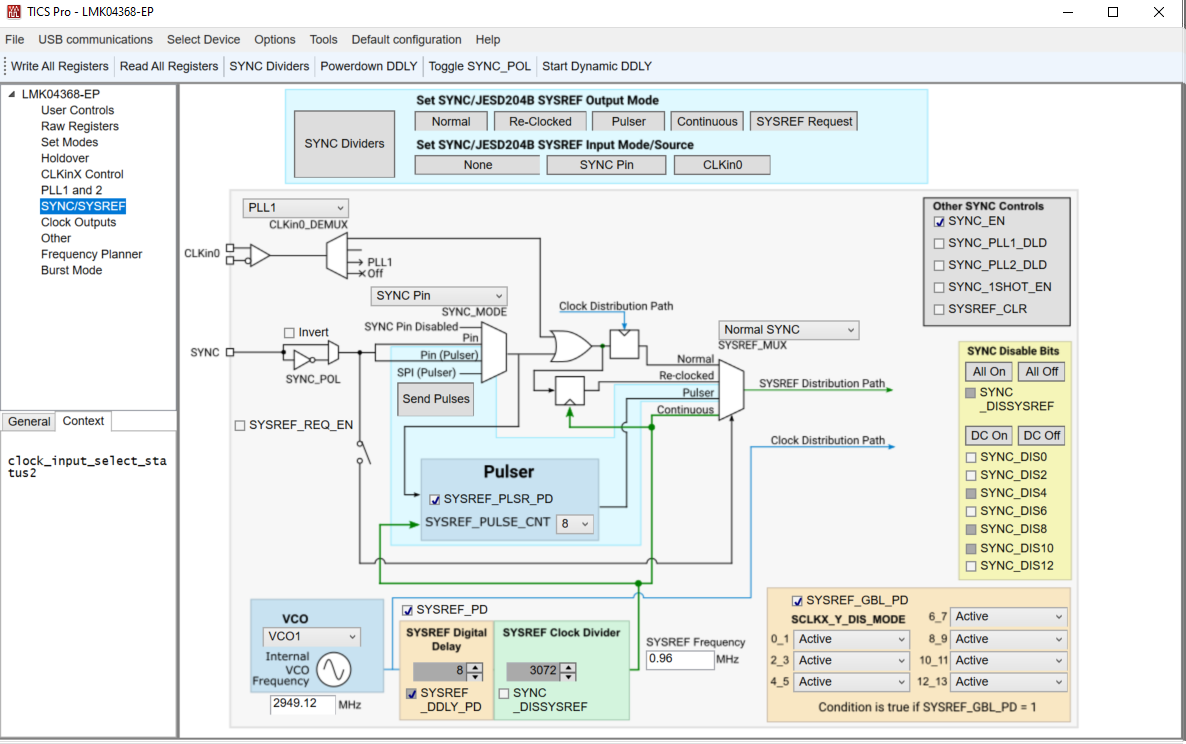
11.8 SYNC / SYSREF Page
The SYNC / SYSREF page allows some mode set buttons for JESD204B features. The SYNC dividers button will stop all SYNC inputs, set normal SYNC mode, enable all dividers for SYNC, issue a SYNC by toggling SYNC_POL, set all dividers to ignore SYNC, then return any other changed parameter to its original state. This is a nice feature to ensure all outputs are synchronized together or to be run after changing the digital delay value which requires a SYNC to update. This functionality is also available on any other page through the toolbar as SYNC Dividers.
To use SYNC or SYSREF, ensure that SYNC_EN = 1. To use SYSREF in continuous, pulser, or reclocked modes, be sure SYSREF_PD = 0.
The SCLKX_Y_DIS_MODE bits allow the clock outputs to be disabled or set to a low state. Values 1 and 2 are only conditionally set by the SYSREF_GBL_PD bit, therefore it is possible to power up/down several SYSREF outputs by programming only one register. When changing between Active (0x00) and Conditional Low (0x01) states, keep the SYSREF_CLR = 1 during the transition to prevent glitch pulses from the SYSREF output.
 Figure 11-8 TICS Pro - SYNC / SYSREF Page