SNAU287 November 2023
- 1
- Description
- Features
- 4
- 1Evaluation Module Overview
- 2Hardware
- 3Software
- 4Hardware Design Files
- 5Additional Information
- 6Related Documentation
3.1.1.1 Frequency Plan
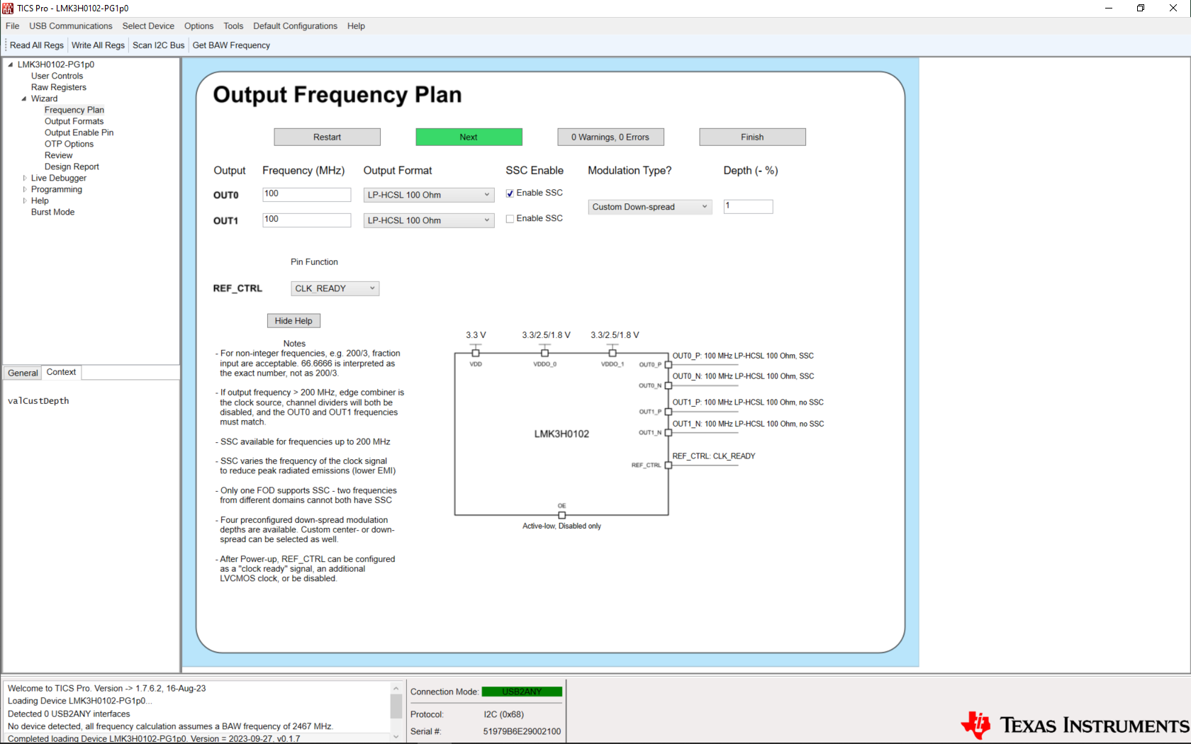
 Figure 3-2 LMK3H0102 Wizard Output
Frequency Plan Page
Figure 3-2 LMK3H0102 Wizard Output
Frequency Plan PageThe Output Frequency Plan page allows for configuring the outputs required for a system. Set each output's clock to the desired frequency and the wizard determines the FOD selection, the channel dividers, and so on for generating the frequency plan. Each output can have the format set on this page, with additional details on the format configuration provided on the Output Formats page.
SSC can be individually enabled/disabled on this page. If either output frequency exceeds 200 MHz, then SSC cannot be used. If SSC is enabled for a specific output, then the modulation type can be set to one of the preconfigured down-spread configurations, a custom down-spread configuration, or a custom center-spread configuration. The custom modulation depth fields accept both positive and negative numbers, so there is no need to worry about specifying the sign of the value.
If the REF_CTRL pin is configured as a REF_CLK output, then options appear for setting the REF_CLK frequency. If only one FOD is used, then any arbitrary frequency between 12.5 MHz and 100 MHz without SSC can be generated, and a text box appears for inputting the desired frequency. If both FODs are in use, then a drop-down menu appears that displays the available frequencies.
The block diagram representation of the LMK3H0102 updates based on the settings that have been selected during configuration generation, and is presented as an aid for visualizing the configuration of the pins on each wizard page.
Clicking the Next button navigates to the next page if there are no errors on the page. If there is an entry that causes an error, then the field is highlighted in red, an error message appears in the status bar at the bottom of the page, a tooltip is added to the field displaying the error message, and the "0 Warnings, 0 Errors" button turns red and updates the error count. If an entry creates a warning, then the same actions occur, but instead the highlight is yellow, and the warning count is updated. Clicking on the Warning/Error button at the bottom displays all of the current errors that exist in the configuration.
Clicking the Restart button clears all fields on all pages that have been entered, and returns to the Wizard page.
Clicking the Finish button assumes the device defaults for all remaining configuration options, and navigates to the Design Review page, where the full configuration can be viewed before writing to the device.