SNAU291A October 2023 – September 2024
4.1.3.1.1 Programmable Output Slew Rate Control
The LMKDB1108 has 16 different slew rates options that can be assigned to the outputs. 0x0 is the fastest slew rate setting and 0xF is the slowest slew rate setting. To set the slew rate of each output, follow these steps:
- There are four different registers, SLEWRATE_OPT#, that can
store up to four different slew rates. Select your desired slew rates by
assigning a value from 0x0 (fastest) to 0xF (slowest) to each SLEWRATE_OPT#
register. The default values set to each SLEWRATE_OPT# register can be found in
Table 4-3.
- For example, if you wanted the two fastest slew
rates and the slowest slew rate, assign 0x0, 0x1, and 0xF to registers
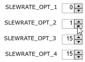
SLEWRATE_OPT#. SLEWRATE_OPT1 = 0x0 (fastest), SLEWRATE_OPT2 = 0x1
(second fastest), SLEWRATE_OPT3 = 0xF (slowest), and SLEWRATE_OPT4 = 0xF
(slowest) as shown in Figure 4-4.
 Figure 4-4 SLEWRATE_OPT#
Assignment Example in TICS Pro
Table 4-3 Default SLEWRATE_OPT_# ValuesRegister Field Name Default Value Default Slew Rate SLEWRATE_OPT_1 0x0 Fastest SLEWRATE_OPT_2 0x6 Fast (default for all outputs) SLEWRATE_OPT_3 0xA Slow SLEWRATE_OPT_4 0xF Slowest - For example, if you wanted the two fastest slew
rates and the slowest slew rate, assign 0x0, 0x1, and 0xF to registers
SLEWRATE_OPT#. SLEWRATE_OPT1 = 0x0 (fastest), SLEWRATE_OPT2 = 0x1
(second fastest), SLEWRATE_OPT3 = 0xF (slowest), and SLEWRATE_OPT4 = 0xF
(slowest) as shown in Figure 4-4.
- Set a slew rate for each output by using the drop-down menus
under the Output Slew Rate Control Section. The default SLEWRATE_OPT#
register assignment for all outputs is SLEWRATE_OPT2, which has a default of
0x6.
- Following the example
from step 1a, if you wanted CLK0, CLK1, CLK2, and CLK3 to have the
fastest slew rate, CLK4 and CLK7 to have the slowest slew rate, and CLK
5 and CLK6 to have the second fastest slew rate, set the drop-down menus
of CLK0, CLK1, CLK2, and CLK3 to OPT_1, CLK4 and CLK7 to OPT_3 or OPT_4,
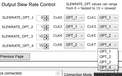
and CLK5 and CLK6 to OPT_2 as shown in Figure 4-5.
 Figure 4-5 Setting Output
Slew Rate Example in TICS Pro
- Following the example
from step 1a, if you wanted CLK0, CLK1, CLK2, and CLK3 to have the
fastest slew rate, CLK4 and CLK7 to have the slowest slew rate, and CLK
5 and CLK6 to have the second fastest slew rate, set the drop-down menus
of CLK0, CLK1, CLK2, and CLK3 to OPT_1, CLK4 and CLK7 to OPT_3 or OPT_4,
and CLK5 and CLK6 to OPT_2 as shown in Figure 4-5.